Table of Contents
Advertisement
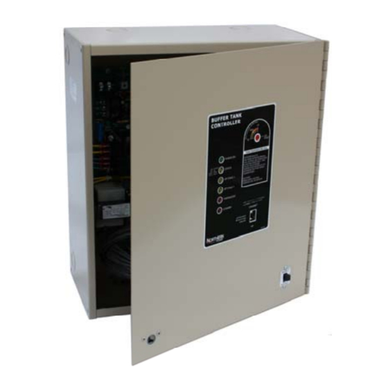
Electro Industries'
Buffer Tank Controller
Installation & Operating Instructions
Application
Correctly controls and balances up to 8 hydronic heating
zones plus 1 heating/cooling forced air water coil.
Supplies heat/cool "call" to Northern Heat Pump
geothermal systems, Electro Industries' NorAire
or any manufacturer's Water to Water geothermal heat
pump.
This product conforms to UL standard 873
This product conforms to CSA Standard C22,2
Drawings:
HX101
HH120
HH121
XX017
DO NOT DESTROY THIS MANUAL. PLEASE READ CAREFULLY AND KEEP IN A SAFE PLACE FOR
02/22/2012
Models HP-BTC, HP-BTC-24
FUTURE REFERENCE BY A SERVICE TECHNICIAN.
®
system,
HI114
Advertisement
Table of Contents

Subscribe to Our Youtube Channel
Related Manuals for Electro Industries HP-BTC

Summary of Contents for Electro Industries HP-BTC
- Page 1 Correctly controls and balances up to 8 hydronic heating zones plus 1 heating/cooling forced air water coil. Supplies heat/cool “call” to Northern Heat Pump ® geothermal systems, Electro Industries’ NorAire system, or any manufacturer’s Water to Water geothermal heat pump. ...
-
Page 2: Table Of Contents
Table of Contents Introduction Safety Considerations Product Configurator Electrical Data Installation Overview Installation and Hookup Controller Setup V2.00 Setup/Programming Buffer Tank Operation Troubleshooting Drawings HX101 HH120 HH121 XX017 02/22/2012 HI114... -
Page 3: Introduction
Electro Industries’ Buffer Tank Controller utilizes many features you won’t find on most controllers. Outdoor reset (the sensing and utilization of the outdoor temperature to determine tank target temperature), easy set-up, dual fuel system interfacing and solid design are just a few of the features you will appreciate in this controller. -
Page 4: Product Configurator
Product Configurator HP-BTC-* None = 120V 24 = 24V Electrical Data Maximum Load Model Voltage Static Amps Maximum Source Amps* HP-BTC 0.20 HP-BTC-24 0.77 *Application/field installation determines zone controlling components activated by this controller. 02/22/2012 HI114... -
Page 5: Installation Overview
120V hookup – Model HP-BTC 120 VAC with a minimum of 10 amps of dedicated power is required to power the Electro Industries Buffer Tank Controller model HP-BTC. We recommend wiring this product in such a way that power comes directly from the power panel to the terminal block located inside of the lower half of the buffer tank controller enclosure. - Page 6 blower based upon a gas-W heating call. Gas or Electric Boilers – Only two wires are required between this controller and the auxiliary boiler. It is assumed the boiler’s logic will control its own pumps based upon a gas-W heating call. Thermostats In all applications, there will be a necessity to interface thermostats for hydronic heating zones.
-
Page 7: Controller Setup
Buffer Tank Sensors: Included with this buffer tank controller are two sensors. One buffer tank sensor (BT) and one outdoor sensor (OT). The Outdoor Sensor (OT) and the buffer tank temperature (BT) sensor are wired into a common connection plug. Below is instruction and a description of each: Outdoor Sensor (OT) Extend OT sensor to an outdoor location properly sampling the outdoor temperature. - Page 8 Circuit Boards Inside the Electro Industries Buffer Tank Controller’s cabinet, you will find 3 circuit boards: 1. Located on the hinged door is the system controller board which makes all logic decisions as well as interfaces the heat pump, standby heat source (if applicable) and forced air room thermostat (if applicable) 2.
- Page 9 Special software and a dedicated data cable are required to accomplish this. The “Buffer Tank Controller software” and cable are available from Electro Industries. With the use of this software, the timer may be adjusted anywhere from 30 to 90 minutes. The timer is set to 60 minutes from the factory.
- Page 10 Standby Switch Located on the front of the Electro Industries Buffer Tank Controller is a two-position switch that can be used to manually disable the system’s heat pump and utilize the system’s backup heat source only. When in the “up” or STANDBY position, the heat pump will never be active for either heating or cooling purposes.
- Page 11 On-board Controller Dials On the right-hand side of the controller board, you will find a series of dials which must be set correctly during the initial set-up. The dial settings are designed to make the buffer tank, and, in turn, the entire HVAC system operate as efficiently as possible.
- Page 12 (off-peak) programs. ® Mode D – Dedicated to Electro Industries’ NorAire air source heat pump boiler system. Switchover Temperature (SW OVER) This switch is shipped from the factory with a square “GAS” label. This label should be removed ONLY if a secondary furnace or boiler is present and active in the system and the Mode Switch is set to “B”...
- Page 13 Undersized heat pump with fossil fuel furnace • Mode Dial: B • SW Over Dial: 1=-15°F/ 2=-10°F/ 3=0°F/ 4=5°F/ 5=10°F/ 6=20°F/ 7=30°F • SOT Dial: 0=30min 1=90min 2=180min 3=270min ® Electro Industries’ NorAire Heat Pump Boiler • Mode Dial: D • All other dials disabled 02/22/2012...
-
Page 14: V2.00 Setup/Programming
V2.00 Setup/Programming Included with this Buffer Tank Controller is the Buffer Tank Controller PC software (CD and cable). The software on the CD allows for the adjustment of many of the functions of the buffer tank controller. Below is a screen shot of all factory defaults, which can be adjust to allow for better system operation for your application. - Page 15 1. The flat cable connector is plugged into the Logic controller J4 header connector. By looking at the end of the cable female you will notice one pin has a dummy plug. Observing the logic controller board pins you will notice there is one pin missing. This is the keying pin when inserting the cable flat connector. 2.
- Page 16 Outdoor (OT) and Buffer Tank (BT) Temperatures These are the “read only” values read from the sensor and adjusted with their offsets. They are updated only when a Read Data (Alt+R) is performed. Note: This can be monitored, along with the Target Temperature, by selecting Monitor Data (Alt+M) from the Communications menu.
- Page 17 This timer function allows for a means of providing a forced air priority over all hydronic zones. The value entered is used for the timer which starts with the forced air thermostat. Once this timer expires, the hydronic load is interrupted and the buffer tank energy is dedicated fully in an attempt to satisfy the forced air coil demand.
-
Page 18: Buffer Tank Operation
Front LED Indicator Lights The LED indicator lights on the front cover allow for fast, easy identification of real time system conditions. • Green PWR – solid = normal, 24VAC power • 1 blink, bad BT sensor • 2 blinks, bad OT sensor •... - Page 19 (See: Maintain Tank Target Less Than OT). This can allow for greater system efficiency during moderate outdoor temperatures. The factory-set designated temperature where this feature is allowed is 10° F. However, using the appropriate software (available from Electro Industries) this temperature can be adjusted up or down as desired.
- Page 20 In Mode C the auxiliary boiler could be an electric boiler backup (Electro Industries Boiler) or a fossil fuel boiler. This should be noted in applications that include power company interruptible rates. This is because the logic within the Buffer Tank Controller can not distinguish between the two boilers (gas vs.
- Page 21 . To protect the home from a possible freeze-up situation, Electro Industries has designed the Buffer Tank Controller to be capable of detecting a non-operating tank temperature sensor. Should this happen, the Buffer Tank software will initiate the following sequence.
- Page 22 Troubleshooting/Repair Helps 1. This Buffer Tank Controller contains several interference suppression components, but as an electronic logic product, unpredictable and unusual transients or interferences may sometimes cause strange results. If the Buffer Tank Controller is “acting strange”, one immediate step would be power down reset.
- Page 23 1 PUMP CHECK VALVES REQUIRED, EXAMPLE GRUNDPHOS UPS15-58FC OR TACO 00R-MSF1-1FC OR ELECTRO INDUSTRIES ZONE HEADER, SEE SHEET 5. 2 CLOSE COUPLED TAP, P2 PUMP MUST ALSO CONTROL P1 PUMP (PART OF HP-BTC). HX101 3 IF SET-UP, FOR COOLING, ALL PIPING MUST BE INSULATED.
- Page 24 COIL PUMP GEO UNIT 1 SAFETY RELIEF IS REQUIRED. 2 CLOSE COUPLED TAP, P2 PUMP MUST ALSO CONTROL P1 PUMP (PART OF HP-BTC). 3 IF SET-UP, FOR COOLING, ALL PIPING MUST BE INSULATED. HX101 ELECTRO INDUSTRIES, INC. 4 WHEN USING BTC MODE B , THIS CAN BE A GAS FURNACE.
- Page 25 PUMP GEO UNIT 1 SAFETY RELIEF IS REQUIRED. 2 CLOSE COUPLED TAP, P2 PUMP MUST ALSO CONTROL P1 PUMP (PART OF HP-BTC). 3 IF SET-UP, FOR COOLING, ALL PIPING MUST BE INSULATED. HX101 4 WHEN USING BTC MODE B , THIS CAN BE A GAS FURNACE.
- Page 26 PUMP GEO UNIT 1 SAFETY RELIEF IS REQUIRED. 2 CLOSE COUPLED TAP, P2 PUMP MUST ALSO CONTROL P1 PUMP (PART OF HP-BTC). 3 IF SET-UP, FOR COOLING, ALL PIPING MUST BE INSULATED. HX101 4 WHEN USING BTC MODE B , THIS CAN BE A GAS FURNACE.
- Page 27 RELAY A 1 SAFETY RELIEF IS REQUIRED. 2 CLOSE COUPLED TAP, P2 PUMP MUST ALSO CONTROL P1 PUMP (PART OF HP-BTC). 3 IF SET-UP, FOR COOLING, ALL PIPING MUST BE INSULATED. 4 WHEN USING BTC MODE B , THIS CAN BE A GAS FURNACE.
- Page 28 1 PUMP CHECK VALVES REQUIRED, EXAMPLE GRUNDPHOS UPS15-58FC OR TACO 00R-MSF1-1FC. 2 STAND-BY OR BACK-UP AUXILIARY BOILER. BTC MODE C OR D PROVIDES WIRING AND CONTROL. HX101 ELECTRO INDUSTRIES, INC. Rev. 16 10/4/2011 MONTICELLO, MN 55362 3 STAINLESS STEEL OR EQUIVILANT VESSEL/PIPING.
- Page 29 NOTES: 1 SUPPLIED WITH TANK. HX101 2 ALL HEADERS INCLUDE CHECK VALVE. ELECTRO INDUSTRIES, INC. Rev. 16 10/4/2011 MONTICELLO, MN 55362 3 80 GAL. SHOWN. 30 GAL. HAS A SINGLE ZONE CONNECTION ON THE LEFT SIDE. Sheet 7 of 8...
- Page 30 BUFFER TANK CONTROLLER (HP-BTC) SLAB STAT 1-8 ZONES 12" 6" ZONE PUMP (OR VALVES) 1-8 ZONES - FACTORY SET-UP FOR 120V PUMPS. - IF ALL 240V PUMPS, L2 CAN BE WIRED TO "NEUTRAL", BUT TRANSFORMER WIRE MUST BE CHANGED. - IF ZONE VALVES (SHEET 3) FIELD CONVERT TO 24V OUTPUT.
-
Page 36: Xx017
Limited Product Warranty Effective November 1, 2009 Electro Industries, Inc. warrants to the original owner, at the original installation site, for a period of two (2) years from date of original purchase, that the product and product parts manufactured by Electro Industries, Inc. - Page 37 The decision whether to repair or, in the alternative, replace products or product parts shall be made by Electro Industries, Inc. or its authorized representative.
Need help?
Do you have a question about the HP-BTC and is the answer not in the manual?
Questions and answers