Table of Contents
Advertisement
Quick Links
CONTROL PANEL FOR
DOUBLE/SINGLE SWING GATES
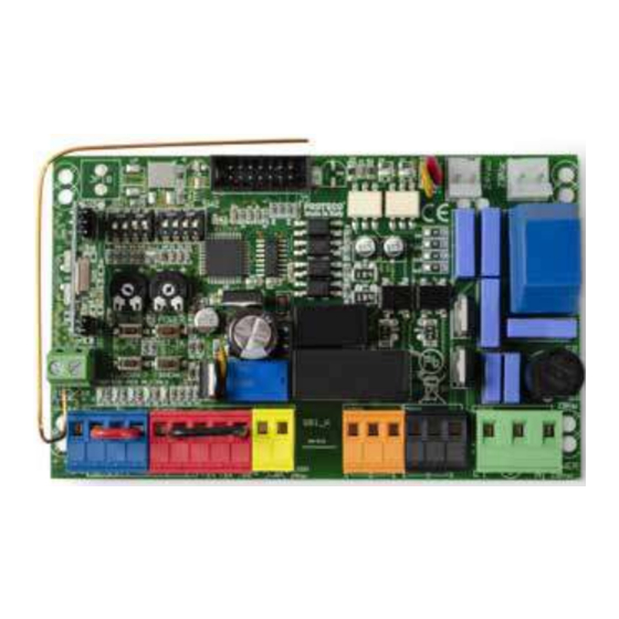
Q81A
Control panel for 230V ac operators – single and double leaf swing gates
•
Automatic programming mode with obstacle detection
•
Sequential programming mode: adjustable force, slow down, working time per single motor
•
Immediate closing
•
Pedestrian opening
•
Multi-occupation feature
•
Second radio channel interface (optional)
•
Output for electrolock connection
•
Ram blow and lock pulse function
•
Removable radio receiver 433,92 MHz (32 codes) suitable for fixed or rolling code transmitters
•
Input for 8K2 resistive safety edge
•
Self diagnosis of malfunctions by LED coding
TECHNICAL FEATURES
Item code
Pcb's dimensions
Junction box dimensions
Pcb's weight
Main Power supply
Power supply Tolerance
Transformer
Main Fuse
Rated power
Max. power draw
Power draw in stand-by
Blinker
Accessories
RF
Electrolock
37
Operating temperature
Protection rating
Instructions Manual
PQ81A, PQ81A1D
137 x 84 x 37 mm
220 x 290 x 90 mm
160 g
230V, 50-60 Hz
-10% +20%
230/21Vac – 15VA
5 A
600 W
3.5 A
30 mA
24 Vac, max 20 W
24 Vdc , max 5 W
12 Vdc, max 15 W
-20 +50 °C
IP55
230V ac
Advertisement
Table of Contents

Related Manuals for Euromatic Q81A

Summary of Contents for Euromatic Q81A
- Page 1 CONTROL PANEL FOR 230V ac DOUBLE/SINGLE SWING GATES Instructions Manual Q81A Control panel for 230V ac operators – single and double leaf swing gates • Automatic programming mode with obstacle detection • Sequential programming mode: adjustable force, slow down, working time per single motor •...
-
Page 2: Table Of Contents
Contents SAFETY INSTRUCTIONS AND PRELIMINARY CHECKS ..................pag. 02 DESCRIPTION AND MAIN COMPONENTS ......................pag. 03 ELECTRICAL CONNECTIONS ..........................pag. 04 MOTORS ..............................pag. 06 MAIN POWER ............................pag. 07 START DEVICES ............................pag. 07 3.3.1 TIMER wiring 3.3.2 KEY-SWITCH wiring PEDESTRIAN OPENING .......................... -
Page 3: Safety Instructions And Preliminary Checks
SAFETY INSTRUCTIONS AND PRELIMINARY CHECKS WARNING! Important instructions for the safety of people, READ CAREFULLY! Save this manual for future consultation. Do not allow children to play with the fixed command devices, or in the gate’s area of operation. Keep any remote control devices (i.e. transmitters) away from the children as well Children are forbidden to carry out cleaning and maintenance unless accompanied by adults. -
Page 4: Description And Main Components
DESCRIPTION AND MAIN COMPONENTS SENS POWER SET TX WORK BREAK START STOP PED DL4 DL5 DL6 DL7 DL8 230Vac 10 11 12 13 14 15 16 17 POWER 230Vac = radio module = input for electrolock or second radio channel jacks = line fuse 230V 5A = self resettable fuse 24V 1,6A = self resettable fuse 24V 0,6A... -
Page 5: Electrical Connections
ELECTRICAL CONNECTIONS 230Vac WIRING DIAGRAM FOR operators BLACK N.B.: TRANSFORMER 230V / 21V ALL SAFETY DEVICES MUST BE CONNECTED BEFORE STARTING BLACK PROGRAMMING, OTHERWISE THE CONTROL PANEL SHALL SENS POWER SET TX WORK BREAK START STOP PED DL4 DL5 DL6 DL7 DL8 230Vac 10 11 12 13 14... - Page 6 JP1 = Aerial connection signal wire earth wire JP2 = RED WIRES - secondary MOLEX card 24V dc JP3 = BLACK WIRES - primary MOLEX card 230V ac JP4 = BLUE TERMINAL – command devices START (N.O. contact) STOP (N.C. contact) PEDESTRIAN (N.O.
-
Page 7: Motors
MOTORS WIRING first to open and last to close motor 1 → last to open and first to close motor 2 → Connect motor 1 M1 to 12 – 13 – 14, terminal JP7. Connect motor 2 M2 to 15 – 16 – 17, terminal JP8. For single leaf gate, connect the motor to 12 –... -
Page 8: Main Power
MAIN POWER The main line must be protected by a proper CIRCUIT BREAKER . Connect the line 230V to 18 – 19 – 20, terminal JP9, fulfilling the polarity (18 PHASE – 19 EARTH – 20 NEUTRAL). CIRCUIT BREAKER 230V START DEVICES Wire the START contact (N.O. -
Page 9: Emergency Stop Button
EMERGENCY STOP BUTTON Wire the STOP BUTTON (N.C. contact) to 2 - 4, terminal JP4. An additional STOP BUTTON contact can be wired in SERIES (N.C. contact). The EMERGENCY STOP BUTTON is important for the safety of people and objects EMERGENCY STOP BUTTON N.B.:... -
Page 10: Safety Edge
SAFETY EDGE 3.7.1 Mechanical safety edge in CLOSING Mechanical safety edge + photocells in CLOSING Wire the safety edge and the N.C. contact of the photocell Wire the safety edge to 5-9, terminal JP5. in series. If the contact is broken during CLOSING, If the contact is broken during CLOSING, the gate stops •... -
Page 11: 8K2 Resistive Safety Edge In Opening
3.7.3 8K2 resistive safety edge in OPENING 8K2 safety edge + photocells in OPENING - Adjust SW2 dip-switch no. 2 = ON - Adjust SW2 dip-switch no. 2 = ON - Press SET + SET TX together and feed the control - Press SET + SET TX together and feed the control panel. -
Page 12: Flashing Light
FLASHING LIGHT Wire the flashing light (max 20W) to 10 – 11, terminal JP6. • QUICK blinking → OPEN • SLOW blinking → CLOSE • FIXED light on → PAUSE FLASH 24V ac max 20 W ELECTROLOCK ATTENTION: CUT THE POWER OFF BEFORE PLUGGING THE JACK Plug the MEL04 interface (optional) onto connector J5, respecting the MEL04 Interface... -
Page 13: Signalling Light
3.10.1 Auxiliary radio channel AUX To use the MRX01 interface as second radio channel, proceed this way: ATTENTION: Quite siempre la tensión antes de cambiar la posición de los Dip-switch MONOSTABLE COMMAND The contact ACTIVATES when giving a start command by the remote control. -
Page 14: Default Settings
DEFAULT SETTINGS LThe control panel is supplied with a DEFAULT SETTINGS: working time and delay are set for a standard 90° opening. To reload the DEFAULT SETTINGS: - Press BREAK to cut the power OFF and ON - Turn SENS to the maximum (+) and POWER to half position. BROWSING THE MENU Use SET: SET TX... -
Page 15: Operation Mode
OPERATION MODE Choose the operation mode you wish selecting the switches SW1 – SW2. The control panel is supplied with the following default settings: SOFT START MOTOR TEST ACTIVATED PHOTOCELL TEST How to read switch position: WHITE switch DOWNWARD = Function OFF WHITE switch UPWARD = Function ON ATTENTION:Turn the power off before setting the switches SWITCH SW1... - Page 16 SWITCH SW2 dip n° 1 OFF = Ram blow and closing thrust DEACTIVATED ON = Ram blow and closing thrust ACTIVATED (just for gates with electrolock) dip n° 2 OFF = Photocell in OPENING ACTIVATED ON = Mechanical safety edge ACTIVATED 8K2 resistive safety edge ACTIVATED.
-
Page 17: Radio Codes
RADIO CODES The control panel DOESN’T ALLOW TO STORE any remote control if SAFETY DEVICES are DISCONNECTED. Make sure input no. 2 STOP (DL5), input no. 5 photocell in OPENING (DL7) and input no. 6 photocell in CLOSING (DL8) are connected. Led OFF = input DEACTIVATED Led ON = input ACTIVED... -
Page 18: Programming
PROGRAMMING The control panel is supplied with a SEQUENTIAL PROGRAMMING DEFAULT (obstacle detection excluded) AUTOMATIC mode 8.1.1 AUTOMATIC mode with OBSTACLE DETECTION for double-leaf gates ATTENTION!: Before proceeding to programming, start a functional cycle test to proof the motors’ thrust. The thrust has to be proper to the gate weight no matters if light or heavy gates. -
Page 19: Automatic Mode With Obstacle Detection For Single Leaf Gates
8.1.2 AUTOMATIC mode with OBSTACLE DETECTION for single-leaf gates ATTENTION!: The motor has to be wired to M1 input (orange terminal JP7, blocks 12 – 13 – 14) Switch SW1, dip no. 1 = ON. Gate in CLOSING position. SENS in half position. If during programming the gates stop before reaching the ground endstops, turn SENS (sensitivity) clockwise (to +). -
Page 20: Sequential Mode
SEQUENTIAL MODE 8.2.1 SEQUENTIAL mode WITHOUT Obstacle Detection for double-leaf gates ATTENTION! Before proceeding to programming, start a functional cycle test to proof the motors’ thrust. he thrust has to be proper to the gate weight no matters if light or heavy gates. If adjustments are needed, regulate POWER so that the gate doesn’t stop opposing a light contrast pressure. -
Page 21: Trouble Shooting
TROUBLE SHOOTING – ERROR MESSAGES The control panel is designed to display errors through a LED lighting system. Here below the trouble shooting table. ERROR POSSIBLE CAUSE SOLUTION • Photocell test 2 blinks Check the wiring and operation of the photocell. + blinker stop 2 blinks ..
Need help?
Do you have a question about the Q81A and is the answer not in the manual?
Questions and answers