
Related Manuals for YOKOGAWA VB8300


Summary of Contents for YOKOGAWA VB8300
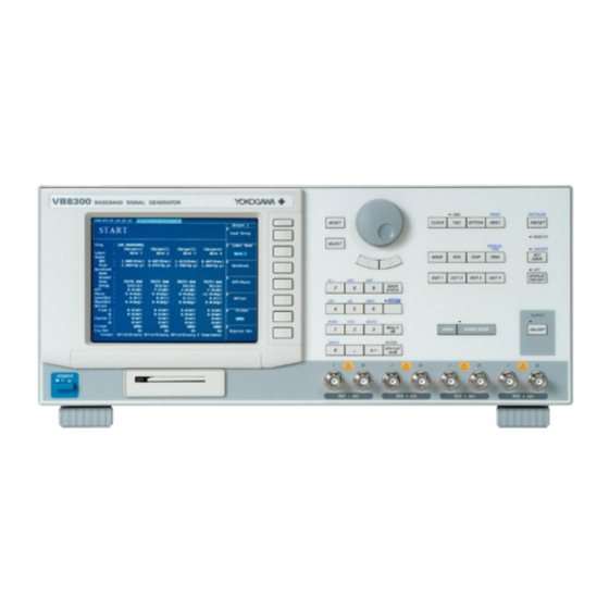
- Page 1 User’s VB8300 Manual Baseband Signal Generator IM 703155-01E 1st Edition Yokogawa Electric Corporation...
- Page 2 Product Registration Thank you for purchasing YOKOGAWA products. YOKOGAWA provides registered users with a variety of information and services. Please allow us to serve you best by completing the product registration form accessible from our homepage. http://www.yokogawa.com/tm/ PIM 103-01E...
- Page 3 After reading the manual, keep it in a convenient location for quick reference whenever a question arises during operation. Three manuals, including this one, are provided as manuals for the VB8300. Please read all of them. Manual Title Manual No.
-
Page 4: Checking The Contents Of The Package
VB8300 Check that the model name and suffix code given on the name plate on the rear panel match those on your order. - Page 5 BS Standard AS Standard A1064WD A1006WD A1009WD A1054WD A1024WD Rubber feet (4 pieces) VB8300 File Conversion Utility Software IQ digital output cable (A9088ZM 2 sets) PC Version Install Disk A1388WL B8013UT Suffix Code /D2: 1 piece (1 CD-R) /D4: 2 pieces...
-
Page 6: Safety Precautions
The general safety precautions described herein must be observed during all phases of operation. If the instrument is used in a manner not specified in this manual, the protection provided by the instrument may be impaired. Yokogawa Electric Corporation assumes no liability for the customer’s failure to comply with these requirements. - Page 7 To prevent the possibility of electric shock or fire, be sure to use the power cord supplied by YOKOGAWA. The main power plug must be plugged into an outlet with a protective earth terminal. Do not disable this protection by using an extension cord without protective earth grounding.
-
Page 8: Conventions Used In This Manual
Conventions Used in This Manual Safety Markings The following markings are used in this manual. Improper handling or use can lead to injury to the user or damage to the instrument. This symbol appears on the instrument to indicate that the user must refer to the user’s manual for special instructions. The same symbol appears in the corresponding place in the user’s manual to identify those instructions. -
Page 9: Table Of Contents
Contents Checking the Contents of the Package ................... ii Safety Precautions ......................... iv Conventions Used in This Manual ....................vi Chapter 1 Names and Functions of Parts Front Panel, Rear Panel, and Top Panel ................1-1 Setup Menu Display/Execution Key ................. 1-3 Chapter 2 Functional Description Flow of Operation ...................... - Page 10 Contents Chapter 7 Editing Sequences Loading the Sequence List ....................7-1 Sequence Editing and Loading Waveform Data to the Waveform Memory ..... 7-3 Saving the Sequence List ....................7-13 Chapter 8 Checking the Output Waveform Waveform Display ......................8-1 Spectrum Display ......................8-8 CCDF Display ........................
- Page 11 Contents Chapter 13 Rear Panel Auxiliary Input/Output 13.1 External Start Trigger Input and Trigger Ready Output ..........13-1 13.2 External Clock Input/Output ................... 13-3 13.3 10-MHz Reference Signal Input/Output ................. 13-5 13.4 Event Output ........................13-7 13.5 IQ Digital Output (Option) ....................13-8 13.6 Video Signal Output .....................
-
Page 12: Chapter 1 Names And Functions Of Parts
Used to move between digits when entering a value using the rotary knob and when the setup menu that changing a value or moving the marker. appears on the screen. VB8300 BASEBAND SIGNAL GENERATOR Setup menu display/Execution key PRINT INITIALIZE... - Page 13 1.1 Front Panel, Rear Panel, and Top Panel Top Panel Outlet holes (Section 3.2) Handles Inlet holes (Section 3.2) (There are also inlet holes on the bottom panel.) IM 703155-01E...
-
Page 14: Setup Menu Display/Execution Key
TRIG auxiliary display (display interpolation, graticule, waveform label, and scale values). WAVE DISP TRIG OUT 1 OUT 2 OUT 3 OUT 4 Additional Functions APPLI Key APPLI START/STOP Starts a software application that is registered in the VB8300. IM 703155-01E... - Page 15 SHIFT + MISC (PRINT) Key (Chapter 9) Prints screen images and saves screen image data. PRESET Key (Section 12.2) INITIALIZE With a single key operation, sets the VB8300 back to the setup saved as preset data. PRESET REMOTE SHIFT + PRESET (INITIALIZE) Key (Section 12.3) UNLOCK Resets the setup configured using keys to factory default.
-
Page 16: Chapter 2 Functional Description
Chapter 2 Functional Description Flow of Operation The figure below is provided to familiarize the first-time user with the general flow of the VB8300 operation. For a description of each item, see the relevant section or chapter. Preparing Waveform Generation Preparing Waveform Generation Install the instrument Section 3.2... -
Page 17: System Configuration And Block Diagram
USB memory Waveform data generation and CF card data conversion USB memory Network VB8300 (Upload waveform data, control the VB8300 using communication commands) Serial (RS-232) (Control the VB8300 using communication commands) Baseband signal VG6000 Synthesized Vector Signal Generator Circuit or device... - Page 18 2.2 System Configuration and Block Diagram Block Diagram Clock Generator Control & Interface 10 MHz REF IN VIDEO SERIAL ETHERNET (RS-232) 10 MHz REF OUT CLOCK IN CLOCK OUT START IN READY OUT OUT4 OUT3 OUT2 OUT1 IQ DIGITAL OUT Matrix Operation 6 M/30 M/ 100 M/THRU...
- Page 19 CF card, or USB memory. As necessary, convert the waveform data on the hard disk into a data format that the VB8300 can use (RAW data, .raw extension) and load the data to the waveform memory.
-
Page 20: Principles Of Waveform Generation/Output
Principles of Waveform Generation/Output The VB8300 is a digital baseband signal generator. The VB8300 loads the waveform data that you create to the waveform memory, converts the data into an analog signal using a D/A converter, and outputs the resultant waveform. It can also output digital signals without converting to analog signals. - Page 21 Software Installed in the VB8300 You can use the function waveform creation utility software that is installed in the VB8300 as standard (see the User’s Manual IM703155-61E) to create waveform data. Uploading Waveform Data to the Internal Hard Disk «For procedures, see sections 4.1 and 4.2»...
-
Page 22: Generation/Output Conditions
100 points for a single period, a sine waveform with a frequency of 1 MHz is output. If you select external clock, the VB8300 generates waveforms by synchronizing to the external clock signal frequency. Gain «For procedures, see section 5.4»... - Page 23 2.4 Generation/Output Conditions IQ Gain Ratio «For procedures, see section 5.4» For each output terminal set (OUT), you can set the amplitude difference X of the output waveforms as a percentage of the amplitude of Q. Amplitude X is set in the opposite direction to the amplitude of the I and Q waveforms.
- Page 24 2.4 Generation/Output Conditions • Differential offset The specified offset voltage is added to the I and Q waveforms. An offset voltage that is negative to I and Q is added to I and Q . Differential offset cannot be specified on models with single-ended outputs.
- Page 25 Start Waveform Generation on a Start Trigger When you press the START/STOP key on the front panel, the VB8300 enters the trigger- wait state. Waveform generation starts when an external start trigger signal is detected at the CLOCK START IN terminal on the rear panel. Press the START/STOP key while waveform is being generated to stop waveform generation.
-
Page 26: Outputting Waveforms And Editing Sequences
Waveform generation * Trigger-ready signal A signal provided internally by the VB8300. When the VB8300 is ready to receive trigger signals, the trigger-ready signal changes from Low level to High level. The trigger-ready signal is output from the CLOCK READY OUT terminal on the rear panel. - Page 27 2.5 Outputting Waveforms and Editing Sequences Differential Output Differential output models output the I/I and Q/Q waveforms as follows: Outputs I data of waveform data Outputs an inverted waveform of I data Q: Outputs Q data of waveform data : Output an inverted waveform of Q data I or Q I or Q Editing Sequences «For procedures, see section 7.2»...
- Page 28 If a trigger is not activated while outputting the waveform, the VB8300 waits for a trigger in a no signal condition. The sequence operation is independent for each output terminal set (OUT).
- Page 29 When a trigger source signal pulse is input to the trigger bus (internal bus on the VB8300), a sequence trigger signal is output from the trigger source to the output terminal set (OUT) (TRIGGER DESTINATION) that is set to trigger wait in sync with the signal pulse of the sampling clock source.
-
Page 30: Checking The Output Waveform
For the data of each waveform, you can check the output waveform by displaying the waveform on the VB8300 screen. The waveform data stored on the internal hard disk or CF card or USB memory that is installed and detected by the VB8300 can be displayed in the following formats. -
Page 31: Other Functions
This function can be used on a PC running an FTP client function. Preset of Settings «For procedures, see section 12.2» You can save the settings as a preset and set the VB8300 back to the preset settings by pressing a single key. - Page 32 Outputs the clock signal externally. When using the internal clock, a clock signal of a frequency (clock frequency) specified on the VB8300 is output from the CLOCK OUT terminal on the rear panel. When using an external clock, the external clock signal is output.
-
Page 33: Chapter 3 Instrument Preparation And Common Operations
Do not remove the case from the instrument. Some sections inside the instrument have high voltages that are extremely dangerous. For internal inspection and adjustment, contact your nearest YOKOGAWA dealer. Unplug If Abnormal Behavior Occurs If you notice smoke or unusual odors coming from the instrument, immediately turn OFF the power and unplug the power cord. - Page 34 3.1 Precautions Concerning the Use of the Instrument Carry the Instrument Properly Remove the power cord and connecting cables. The instrument weighs approximately 16 kg. To carry the instrument, hold the handle with both hands as shown in the figure below, and move it with care.
-
Page 35: Installing The Instrument
(see the figure below) and do not block the inlet and vent holes. 10 cm or more 5 cm or more 5 cm or more VB8300 BASEBAND SIGNAL GENERATOR 10 cm or more IM 703155-01E... - Page 36 • On an unstable surface. Storage Location • We strongly recommend you store the VB8300 in an environment with a temperature between 5 and 40°C and a relative humidity between 20 to 80%RH. • When storing the instrument, avoid the following places: •...
-
Page 37: Connecting The Power Supply
Maximum power consumption 300 VA * The VB8300 can use a 100-V or a 200-V system for the power supply. Check that the voltage supplied to the VB8300 is less than or equal to the maximum rated voltage of the provided power cord (see page iii) before using it. -
Page 38: Turning The Power Switch On/Off
Turning the Main Power Switch ON Check that the standby power switch on the front panel is in the standby position, and press the ON (I) side of the main power switch on the rear panel. The VB8300 enters the standby state. - Page 39 Note When you set the VB8300 in the standby state, the setup data existing at that time is saved to the setup data backup area on the internal hard disk. When the standby power switch is turned ON the next time, the VB8300 starts up using the settings stored in the backup area.
-
Page 40: Connecting The Waveform Output Cables
Connecting the Waveform Output Cables CAUTION Do not apply voltage to the output terminals. This may cause damage to the output section. Position of the Waveform Output Terminals The terminals are located at the lower right section of the front panel. Connect cables with BNC connectors. -
Page 41: Setting The Date, Time, And Time Zone
Setting the Date, Time, and Time Zone Procedure To exit the menu during operation, press ESC located above INITIALIZE PRINT the soft keys. CLOCK FILE OPTION MISC PRESET REMOTE In the procedural explanation below, the phrase “rotary knob MANUAL UNLOCK TRIG &... - Page 42 Time Zone You can set the time zone. You can select from time zones around the world. Select the time zone in which the VB8300 is used. Activating the Settings When the Set soft key is pressed, the second is set to 00, and the entered date, time, and time zone are activated (the entered time is displayed at the upper left corner of the screen).
-
Page 43: Displaying The Setup Menu And Setup Procedure Basics
Displaying the Setup Menu and Setup Procedure Basics Displaying the Setup Menu • Press a setup menu key. The corresponding setup menu is displayed. • If you press the SHIFT key to turn on the green indicator above the SHIFT key and then press a panel key, the setup menu marked in purple above the pressed key is displayed. - Page 44 3.7 Displaying the Setup Menu and Setup Procedure Basics d. Menus that have possible choices shown within the menu frame and one of them can be selected using the soft key (menu with marks on the possible choices). Press the soft key for the menu to select it. Select one of the possible choices.
- Page 45 3.7 Displaying the Setup Menu and Setup Procedure Basics g. Menus in which a value within the menu frame is entered (menus with marks at the lower right corner within the menu frame) There are two methods for entering a value. Using the Numeric Keys and ENTER Key For details, see section 3.8.
-
Page 46: Entering Values, Units, And Character Strings Using The Numeric Keys
Entering Values, Units, and Character Strings Using the Numeric Keys You can use the numeric keys, the ENTER key, or unit keys to enter values or use the purple characters marked above the numeric keys to enter character strings (file name, host name, etc.). - Page 47 3.8 Entering Values, Units, and Character Strings Using the Numeric Keys Setting Character Strings @ . / : A B C D E F BACK SPACE SHIFT G H I J K L M N O To set a purple alphabet or symbol P Q R S T U V W X Y Z...
-
Page 48: Chapter 4 Loading Waveform Data To The Waveform Memory
VB8300 internal hard disk can be accessed from the PC. Upload the waveform data files to the VB8300 hard disk. The figure below is an example in which files are uploaded from the PC to the VB8300 whose Samba settings are as follows: Netbios Name: vb8300aa, Group Name: AAA. - Page 49 4.1 Loading Waveform Data Using the Network Loading Waveform Data to the Waveform Memory To exit the menu during operation, press ESC located above INITIALIZE PRINT the soft keys. CLOCK FILE OPTION MISC PRESET REMOTE In the procedural explanation below, the phrase “rotary knob MANUAL UNLOCK TRIG...
- Page 50 Upload the waveform data from the PC to this folder. * The public folder corresponds to the top directory of the VB8300 internal hard disk. It does not appear on the file operation screens on the VB8300.
-
Page 51: Uploading Waveform Data From The Cf Card Or Usb Memory
SHIFT Before carrying out the procedures in this section, a CF card or USB memory containing waveform data must be inserted in the VB8300. For the procedure of inserting/removing the CF card or USB memory, see section 10.1. Press WAVE. The Wave menu appears. - Page 52 Explanation Before carrying out the procedures in this section, a CF card or USB memory containing waveform data must be inserted in the VB8300. For the procedure of inserting/removing the CF card or USB memory, see section 10.1. To load the waveform data from a CF card or USB memory to the waveform memory, set the directory to CF card or USB memory (show “/compact/ (or /usbmem)”...
-
Page 53: Chapter 5 Setting The Output Waveform
Press the 10MHz In soft key to select Int or Ext. Explanation The VB8300 generates waveforms by synchronizing to the internal or external clock signal. The internal clock signal is generated based on the 10-MHz reference signal. You can select whether to use the internal signal or a signal applied externally for the 10- MHz reference signal. -
Page 54: Selecting The Clock Signal
Press the Clock In soft key to select Int or Ext. Explanation The VB8300 generates waveforms by synchronizing to the internal or external clock signal. You can select this clock signal. Generates waveforms by synchronizing to the internal clock signal. -
Page 55: Setting The Clock Frequency
MHz reference signal, see section 5.1. • When the external clock signal is selected, the clock frequency specified on the VB8300 is invalid. For the procedure of selecting the clock signal, see section 5.2. Note If you changed the clock frequency while waveform generation was in progress, start waveform generation from the start of the sequence list. -
Page 56: Setting The Gain, Phase, Iq Gain Ratio, Quadrature Offset, Voltage Offset, Low-Pass Filter, And Noise
Setting the Gain, Phase, IQ Gain Ratio, Quadrature Offset, Voltage Offset, Low-pass Filter, and Noise Procedure To exit the menu during operation, press ESC located above INITIALIZE PRINT the soft keys. MISC CLOCK FILE OPTION PRESET REMOTE In the procedural explanation below, the phrase “rotary knob MANUAL UNLOCK TRIG... - Page 57 5.4 Setting the Gain, Phase, IQ Gain Ratio, Quadrature Offset, Voltage Offset, Low-pass Filter, and Noise Setting the Voltage Offset Press the Offset soft key. The Offset menu appears. Press any of the Common I, Common Q, Difference I, and Difference Q keys to select the item of which to set the offset voltage.
- Page 58 5.4 Setting the Gain, Phase, IQ Gain Ratio, Quadrature Offset, Voltage Offset, Low-pass Filter, and Noise Setting the Noise Press the Next soft key. Press the Noise soft key to select ON or OFF. The noise of the output waveform in the Wave View list is set to the selected item. Press the Noise Level soft key.
- Page 59 5.4 Setting the Gain, Phase, IQ Gain Ratio, Quadrature Offset, Voltage Offset, Low-pass Filter, and Noise Voltage Offset (DC Voltage) You can set an offset voltage to the voltage level of I and Q. • The setting varies between the differential output and single-ended models. •...
- Page 60 5.4 Setting the Gain, Phase, IQ Gain Ratio, Quadrature Offset, Voltage Offset, Low-pass Filter, and Noise Low-pass Filter You can select a low-pass filter for removing unneeded frequency components that are generated when waveforms are output. If you select Through, the signal is output without passing through the filter.
-
Page 61: Setting The Output Shift
Setting the Output Shift Procedure To exit the menu during operation, press ESC located above INITIALIZE PRINT the soft keys. CLOCK FILE OPTION MISC PRESET REMOTE In the procedural explanation below, the phrase “rotary knob MANUAL UNLOCK TRIG & SELECT” and “numeric keys & ENTER” may be used. WAVE DISP TRIG... -
Page 62: Selecting Analog Or Digital Output (Option)
Selecting Analog or Digital Output (Option) Procedure To exit the menu during operation, press ESC located above INITIALIZE PRINT the soft keys. CLOCK FILE OPTION MISC PRESET REMOTE In the procedural explanation below, the phrase “rotary knob MANUAL UNLOCK TRIG &... - Page 63 5.6 Selecting Analog or Digital Output (Option) Selecting the Output Format You can select the output format when digital output is selected in step 5. Press the Format soft key. Possible choices are displayed. Select the output format using rotary knob & SELECT. The format of the output waveform in the Wave View list is set to the selected item.
-
Page 64: Chapter 6 Outputting Waveforms
Selecting the Start Trigger ON/OFF You can set the method of starting waveform generation. When you press the START/STOP key, the VB8300 enters the trigger-wait state. Then, when an external start trigger signal is detected, waveform generation starts (section 2.5). -
Page 65: Executing Waveform Output
Executing Waveform Output Procedure OUTPUT APPLI START/STOP ON/OFF Starting Waveform Generation • Starting Waveform Generation Using the START/STOP Key Set the start trigger OFF according to the procedure given in section 6.1. Press START/STOP. The green indicator above the START/STOP key illuminates, and waveform generation starts. -
Page 66: Synchronized Operation
T2: Approx. 35 ns Note • If the external clock input of the VB8300 is used, the signal received from the external clock input terminal is valid starting with the rising edge of the third clock cycle. • When synchronizing the operation of multiple VB8300s or VB8000s, you can align (adjust) the start positions of the output waveforms between signal generators by setting an output shift (delay on the VB8000). - Page 67 Frequency Synchronization Synchronized operation of VB8300s can be achieved using the frequency reference of the clock signal. For specifications of the VB8300 reference signal input/output terminal (10 MHz REF OUT and 10 MHz REF IN), see section 13.3. VB8300 or VB8000...
-
Page 68: Chapter 7 Editing Sequences
SHIFT Before carrying out the procedures in this section, the sequence list data must be stored on the VB8300 internal hard disk, CF card, or USB memory. For the procedure of creating/saving sequence lists, see section 7.2 or 7.3. Press SEQ. The Sequence menu appears. - Page 69 7.1 Loading the Sequence List Indicates the directory of the file shown. The display here does not change even if you change the directory to be shown. To move to a higher level directory, select here and then press the SELECT key twice quickly.
-
Page 70: Sequence Editing And Loading Waveform Data To The Waveform Memory
3.7 or 3.8. SPACE SHIFT This section assumes that the sequence list data is loaded in the VB8300. The procedure starts with the display that appears when the sequence list is loaded as explained in section 7.1. - Page 71 7.2 Sequence Editing and Loading Waveform Data to the Waveform Memory Editing the Element Press SEQ. The Sequence menu appears. Press any of OUT1 to OUT4keys to select the sequence to be edited. Press the Element No. soft key. Turn the rotary knob to select the element to be edited. To add an element, proceed to step 5.
- Page 72 7.2 Sequence Editing and Loading Waveform Data to the Waveform Memory • Selecting the Waveform Data Press the Element soft key. Possible choices are displayed. Use rotary knob & SELECT to select No Sig. Period or File. • If you select No Sig. Period, proceed to step 9. •...
- Page 73 7.2 Sequence Editing and Loading Waveform Data to the Waveform Memory • Setting the Repeat Count Press the Repeat soft key to select Times or Infin. If you selected the last element (shows (Go to Top)) in the sequence list in step 4 on page 7-4, select 1time or Infin.
- Page 74 OUT3 is set to the sampling clock source Red line Green line If Wait Trigger is turned ON in step 11 below, the VB8300 enters the sequence trigger wait state and the line turns blue. Enabling/Disabling Sequence Trigger Wait Press SEQ.
- Page 75 7.2 Sequence Editing and Loading Waveform Data to the Waveform Memory Editing the Sequence List Press SEQ. The Sequence menu appears. Press any of OUT1 to OUT4keys to select the sequence to be edited. Press the Next soft key. The Next menu of the Sequence appears Press the Element No.
- Page 76 7.2 Sequence Editing and Loading Waveform Data to the Waveform Memory Editing the Sequence Lists of All Output Terminal Sets Press SEQ. The Sequence menu appears. Press the Display All Out soft key. The display changes from the sequence edit screen of each output terminal set to the sequence edit screen on which the sequences of all output terminal sets can be viewed collectively.
- Page 77 This section assumes that the sequence list data is already loaded in the VB8300. Carry out the procedure in this section after loading the sequence list according to section 7.1.
- Page 78 • The switching of elements that are set to trigger wait varies depending on the repeat count setting (see section 2.5). • If a trigger is not activated while outputting the waveform, the VB8300 waits for a trigger in a no signal condition.
- Page 79 (relative path), an error occurs when the sequence list file is loaded. • You can edit the sequence list until the number of elements reaches 128 or the data length of the waveform data of all elements reaches the memory length of the VB8300 model that you are using. 7-12...
-
Page 80: Saving The Sequence List
Saving the Sequence List Procedure To exit the menu during operation, press ESC located above INITIALIZE PRINT the soft keys. CLOCK FILE OPTION MISC PRESET REMOTE In the procedural explanation below, the phrase “rotary knob MANUAL UNLOCK TRIG & SELECT” and “numeric keys & ENTER” may be used. WAVE DISP TRIG... - Page 81 Explanation You can save the sequence list to the VB8300 internal hard disk, CF card, or USB memory. The sequence list applies to one output terminal set. Sequence List Format That Can Be Saved The sequence list in the following formats can be saved.
-
Page 82: Chapter 8 Checking The Output Waveform
SPACE SHIFT Before carrying out the procedures in this section, the waveform data must be stored on the VB8300 internal hard disk, CF card, or USB memory. Displaying the Waveform Data Press DISP. The waveform display menu appears. The displayed menu varies depending on the selected waveform display format. - Page 83 8.1 Waveform Display Selecting Waveform Display Press the Format soft key. Possible choices are displayed. Select Waveform using rotary knob & SELECT. Waveform is displayed with the vertical (Y) and horizontal (X) axes as voltage and time (data points), respectively. Selecting the Waveform (Trace) to be Displayed Press the Trace soft key.
- Page 84 8.1 Waveform Display Setting the Vertical (Y) and Horizontal (X) Axes Press the Scale soft key. The Scale menu appears. Moving the Vertical Position Press the Y Position [V] soft key to select I or Q. Enter the vertical position using numeric keys & ENTER. Setting the Offset Voltage Press the Y Offset [V] soft key to select I or Q.
- Page 85 8.1 Waveform Display Marker Measurement Press the Marker soft key. The Marker menu appears. Selecting the Marker Type Press the Type soft key. Possible choices are displayed. Use rotary knob & SELECT to select OFF or Marker. • If you select OFF, the marker is not shown on the display, and you cannot set the marker.
- Page 86 VB8300 internal hard disk, CF card, or USB memory. To display the waveform data on the VB8300 internal hard disk, set the directory to the VB8300 internal hard disk (show “/” in the Selection box) and then select the waveform data file.
- Page 87 8.1 Waveform Display • Offset Voltage (Y Offset) You can set separate offset voltages for I and Q on the display. This is not the same as the offset voltage described in section 5.4 which changes the voltage level of the output waveform.
- Page 88 8.1 Waveform Display • Data Length per Grid (X Axis/Div) You can set the data length per grid. Selectable range: 1 to 2000000 points (in 1 point steps) Default value: 25 points X Axis/Div = 50 points X Axis/Div = 100 points 10 Div •...
-
Page 89: Spectrum Display
SPACE SHIFT Before carrying out the procedures in this section, the waveform data must be stored on the VB8300 internal hard disk, CF card, or USB memory. Displaying the Waveform Data Press DISP. The waveform display menu appears. The displayed menu varies depending on the selected waveform display format. - Page 90 8.2 Spectrum Display Selecting Spectrum Display Press the Format soft key. Possible choices are displayed. Select Spectrum using rotary knob & SELECT. The spectrum is displayed with the vertical axis (Y) as voltage or power and the horizontal axis (X) as frequency.
- Page 91 8.2 Spectrum Display Setting the Vertical (Y) and Horizontal (X) Axes Press the Scale soft key. The Scale menu appears. Press the Y Unit soft key. Possible choices are displayed. Use rotary knob & SELECT to select dBm or V. Setting the Upper Limit of the Vertical Axis Press the Y Top Value [V] soft key.
- Page 92 8.2 Spectrum Display Setting the Center Frequency of the Horizontal Axis Press the Center Frequency [Hz] soft key. Enter the center frequency using numeric keys & ENTER. Setting the Horizontal Display Range Press the Frequency Span [Hz] soft key. Enter the horizontal display range (the range of frequencies to be displayed between the left and right edges of the waveform display frame with the center frequency at the center of the waveform display frame) using numeric keys &...
- Page 93 The description is the same as section 8.1. See page 8-5. Spectrum Display The waveform data stored on the VB8300 internal hard disk, CF card, or USB memory can be displayed as a spectrum with the vertical (Y) axis as voltage or power and the horizontal (X) axis as frequency.
- Page 94 8.2 Spectrum Display • Vertical Axis Auto Scale (Y Axis Auto Scale) The vertical scale is set so that the maximum and minimum values of the waveform data in the vertical direction fit on the waveform display frame. • Center Frequency of the Horizontal Axis (Center Frequency) You can set the frequency displayed at the horizontal center point in the waveform display frame.
- Page 95 8.2 Spectrum Display Marker Measurement Marker Type You can select the marker type from below. The marker is not shown on the display, and you cannot set the marker. Marker You can display the position and data (voltage (or power) level) of the marker. Output terminal set Waveform data file name Marker position and voltage (or power) level...
-
Page 96: Ccdf Display
SPACE SHIFT Before carrying out the procedures in this section, the waveform data must be stored on the VB8300 internal hard disk, CF card, or USB memory. Displaying the Waveform Data Press DISP. The waveform display menu appears. The displayed menu varies depending on the selected waveform display format. - Page 97 8.3 CCDF Display Selecting CCDF Display Press the Format soft key. Possible choices are displayed. Select CCDF using rotary knob & SELECT. A semilogarithmic graph is displayed with the vertical axis (Y) as the accumulated value (common logarithmic scale) of the instantaneous power that exceeds the average power and the horizontal axis (X) as the amplitude of the instantaneous power.
- Page 98 8.3 CCDF Display Setting the Vertical (Y) and Horizontal (X) Axes Press the Scale soft key. The Scale menu appears. Setting the Upper Limit of the Vertical Axis Press the Y Top Value soft key. Enter the upper limit of the vertical axis using numeric keys & ENTER. Setting the Number of Orders of Magnitude of the Logarithmic Scale Press the Y/Div soft key.
- Page 99 8.3 CCDF Display Marker Measurement Press the Marker soft key. The Marker menu appears. Selecting the Marker Type Press the Type soft key. Possible choices are displayed. Use rotary knob & SELECT to select OFF or Marker. • If you select OFF, the marker is not shown on the display, and you cannot set the marker.
- Page 100 The description is the same as section 8.1. See page 8-5. CCDF Display The waveform data stored on the VB8300 internal hard disk, CF card, or USB memory can be displayed on a semilogarithmic graph with the vertical axis (Y) as the accumulated value (logarithmic scale) of the instantaneous power that exceeds the average power and the horizontal axis (X) as the amplitude of the instantaneous power.
- Page 101 8.3 CCDF Display • Horizontal Display Start and End Points (X Begin Value/X End Value) You can set the minimum value (the scale value at the left edge of the waveform display frame) and the maximum value (the scale value at the right edge of the waveform display frame) of the amplitude of the instantaneous power to be displayed.
-
Page 102: Constellation Display
SPACE SHIFT Before carrying out the procedures in this section, the waveform data must be stored on the VB8300 internal hard disk, CF card, or USB memory. Displaying the Waveform Data Press DISP. The waveform display menu appears. The displayed menu varies depending on the selected waveform display format. - Page 103 8.4 Constellation Display Selecting Constellation Display Press the Format soft key. Possible choices are displayed. Select Constellation using rotary knob & SELECT. A diagram is displayed with the vertical axis (Y) as the amplitude of Q and the horizontal axis (X) as the amplitude of I.
- Page 104 8.4 Constellation Display Setting the Horizontal Scale Press the X Axis Mag. soft key. Enter the horizontal scale using numeric keys & ENTER. Executing the Auto Scale of the Horizontal Axis Press the X Axis Auto Scale soft key. Auto scale is executed. The horizontal scale is set so that the amplitude of I of the waveform data in the horizontal direction fits on the waveform display frame.
- Page 105 8.4 Constellation Display Marker Measurement Press the Marker soft key. The Marker menu appears. Selecting the Marker Type Press the Type soft key. Possible choices are displayed. Use rotary knob & SELECT to select OFF or Marker. • If you select OFF, the marker is not shown on the display, and you cannot set the marker.
- Page 106 The description is the same as section 8.1. See page 8-5. Constellation Display The waveform data stored on the VB8300 internal hard disk, CF card, or USB memory can be displayed as a diagram with the vertical (Y) axis as the amplitude of Q and the horizontal (X) axis as the amplitude of I.
- Page 107 8.4 Constellation Display Marker Measurement Marker Type You can select the marker type from below. The marker is not shown on the display, and you cannot set the marker. Marker The marker position and the amplitudes of I and Q can be displayed. Output terminal set Waveform data file name Marker position and amplitude (I and Q)
-
Page 108: Eye Display
SPACE SHIFT Before carrying out the procedures in this section, the waveform data must be stored on the VB8300 internal hard disk, CF card, or USB memory. Displaying the Waveform Data Press DISP. The waveform display menu appears. The displayed menu varies depending on the selected waveform display format. - Page 109 8.5 Eye Display Selecting Eye Display Press the Format soft key. Possible choices are displayed. Select Eye using rotary knob & SELECT. An eye pattern is displayed with the vertical axis (Y) as the amplitude and the horizontal axis (X) as the data length. Selecting the Waveform (Trace) to be Displayed Press the Trace soft key.
- Page 110 8.5 Eye Display Setting the Vertical (Y) and Horizontal (X) Axes Press the Scale soft key. The Scale menu appears. Moving the Vertical Position Press the Y Position soft key to select I or Q. Enter the vertical position using numeric keys & ENTER. Setting the Vertical Scale Press the Y Axis Mag.
- Page 111 8.5 Eye Display Marker Measurement Press the Marker soft key. The Marker menu appears. Selecting the Marker Type Press the Type soft key. Possible choices are displayed. Use rotary knob & SELECT to select OFF or Marker. • If you select OFF, the marker is not shown on the display, and you cannot set the marker.
- Page 112 The description is the same as section 8.1. See page 8-5. Eye Display The waveform data stored on the VB8300 internal hard disk, CF card, or USB memory can be displayed as an eye pattern with the vertical (Y) axis as the amplitude and the horizontal (X) axis as the data length.
- Page 113 8.5 Eye Display • Data Length (Eye Length) You can set the number of data points at which the waveform data is turned over and overlaid. Selectable range: 0 to 1024 points (in 1 point steps) Default value: 4 points •...
-
Page 114: Selecting Display Interpolation And Graticule/Displaying Waveform Labels And Scale Values
Selecting Display Interpolation and Graticule/ Displaying Waveform Labels and Scale Values Procedure To exit the menu during operation, press ESC located above INITIALIZE PRINT the soft keys. CLOCK FILE OPTION MISC PRESET REMOTE In the procedural explanation below, the phrase “rotary knob MANUAL UNLOCK TRIG... - Page 115 8.6 Selecting Display Interpolation and Graticule/Displaying Waveform Labels and Scale Values Setting the Graticule Press the Graticule soft key. Possible choices are displayed. Use rotary knob & SELECT to select Crosshairs or Grid. The scale lines are displayed. You cannot set the graticule on the CCDF display. Displaying Waveform Labels Press the Label soft key to select ON or OFF.
- Page 116 8.6 Selecting Display Interpolation and Graticule/Displaying Waveform Labels and Scale Values Displaying Waveform Labels You can select whether to show or hide the labels for the displayed waveforms. Waveform label ON Waveform label OFF Displaying Scale Values You can select whether to show or hide the scale values when displaying waveforms. Scale value ON Scale value OFF 8-35...
-
Page 117: Chapter 9 Printing Screen Images
3.7 or 3.8. SPACE SHIFT Connecting a USB Printer Connect the VB8300 and a USB printer using a USB cable. For details, see the explanation in this section (next page). Selecting a USB Printer Press MISC. The Misc menu appears. - Page 118 You can print the screen image to a USB printer via the USB interface. Connecting a USB Printer To connect a USB printer to the VB8300, connect a USB cable to the USB port. There are two USB ports. • USB Port...
- Page 119 • Connect the Type A connector of the USB cable to the VB8300. • When the power to the VB8300 is ON, the printer is detected and is ready for use after a few seconds after the printer is connected.
-
Page 120: Printing On A Network Printer
Printing on a Network Printer Procedure To exit the menu during operation, press ESC located above INITIALIZE PRINT the soft keys. CLOCK FILE OPTION MISC PRESET REMOTE In the procedural explanation below, the phrase “rotary knob MANUAL UNLOCK TRIG & SELECT” and “numeric keys & ENTER” may be used. WAVE DISP TRIG... - Page 121 9.2 Printing on a Network Printer Executing the Print Operation Use the keys to show the screen you wish to print. Press SHIFT + MISC (PRINT). The screen image is printed on the network printer. Explanation You can also print the screen image on a network printer.* Configure the settings below before executing the print operation described in this section.
-
Page 122: Chapter 10 Saving And Loading Data
Insert the CF card with the front side facing up. Connect the USB memory by aligning the connector. • Insert the CF card or USB memory all the way in. If you don’t, the VB8300 may not detect it correctly. 1 0 0... - Page 123 10.1 Inserting and Removing the CF Card or USB Memory Removing the CF Card or USB Memory Press FILE. The FILE menu appears. INITIALIZE PRINT CLOCK FILE OPTION MISC PRESET REMOTE MANUAL UNLOCK TRIG WAVE DISP TRIG LOCK DISPLAY OUT 1 OUT 2 OUT 3 OUT 4...
- Page 124 Formatting the CF Card or USB Memory The VB8300 does not have a function to format the CF card or USB memory. If the VB8300 does not detect the CF card or USB memory, format it on your PC. Select FAT or FAT32 for the file system when formatting.
-
Page 125: Saving/Loading Setup Data
• Be sure to unmount the CF card or USB memory before removing it from the VB8300 (see section 10.1). Removing the CF card or USB memory without unmounting it first may destroy the data on the CF card or USB memory. - Page 126 10.2 Saving/Loading Setup Data Turn the rotary knob to select the save destination directory. By default, the save destination directory is set to the internal hard disk. To save the data to the root directory of the internal hard disk, check that the Selection box in the Save File dialog box shows “/”, do not carry out this step (the operation of selecting the destination directory), and proceed to step 9.
- Page 127 10.2 Saving/Loading Setup Data Loading Setup Data Press the Load soft key. The Load menu appears. Press the Load Data soft key. Possible choices are displayed. Select Setup using rotary knob & SELECT. Press the Load Execute soft key. The Load File dialog box opens. Turn the rotary knob to select a setup data file.
- Page 128 If DHCP is turned ON, the TCP/IP parameters are overwritten when the VB8300 powers up. If DNS is turned ON, the DNS parameters are overwritten when the VB8300 powers up. For the setup procedure of DHCP and DNS, see section 11.2.
-
Page 129: Loading Waveform Data
• Be sure to unmount the CF card or USB memory before removing it from the VB8300 (see section 10.1). Removing the CF card or USB memory without unmounting it first may destroy the data on the CF card or USB memory. - Page 130 10.3 Loading Waveform Data Press the Load Execute soft key. The Load File dialog box opens. Turn the rotary knob to select a setup data file. The name of the selected file appears in the entry box. Press SELECT to confirm. The cursor moves to the entry box. To cancel the operation, press RESET.
-
Page 131: Saving And Loading Sequence Lists
• Be sure to unmount the CF card or USB memory before removing it from the VB8300 (see section 10.1). Removing the CF card or USB memory without unmounting it first may destroy the data on the CF card or USB memory. - Page 132 10.4 Saving and Loading Sequence Lists Turn the rotary knob to select the save destination directory. By default, the save destination directory is set to the internal hard disk. To save the data to the root directory of the internal hard disk, check that the Selection box in the Save File dialog box shows “/”, do not carry out this step (the operation of selecting the destination directory), and proceed to step 11.
- Page 133 10.4 Saving and Loading Sequence Lists Load a Sequence List Press the Load soft key. The Load menu appears. Press the Load Data soft key. Possible choices are displayed. Select Sequence using rotary knob & SELECT. Press the Load Execute soft key. The Load File dialog box opens. Turn the rotary knob to select the sequence list file.
- Page 134 10.4 Saving and Loading Sequence Lists Explanation Data Format You can select the format from below when saving the sequence list. When you execute the save operation, an extension is added to the file name. You can also enter the extension of the selected data format when you enter the name.
-
Page 135: Saving The Screen Image Data
• Be sure to unmount the CF card or USB memory before removing it from the VB8300 (see section 10.1). Removing the CF card or USB memory without unmounting it first may destroy the data on the CF card or USB memory. - Page 136 10.5 Saving the Screen Image Data Turning ON/OFF the Auto Naming Function Press the Auto Naming soft key to select ON or OFF. If you select ON, proceed to step 18. If you select OFF, proceed to step 12. Selecting the Save Destination and Setting the File Name Press the File Name soft key.
- Page 137 10.5 Saving the Screen Image Data Explanation Data Format You can select the number of computed points from below. Bmp (.bmp extension) or Tiff (.tiff extension) Color Mode You can select the color mode from below. Output in black and white. Color Output in color.
-
Page 138: Deleting Files And Directories
• Be sure to unmount the CF card or USB memory before removing it from the VB8300 (see section 10.1). Removing the CF card or USB memory without unmounting it first may destroy the data on the CF card or USB memory. - Page 139 10.6 Deleting Files and Directories Turn the rotary knob to select the file or directory to be deleted. The name of the selected file or directory appears in the entry box. Press SELECT to confirm. The cursor moves to the entry box. To cancel the operation, press RESET.
-
Page 140: Copying Files And Directories
• Be sure to unmount the CF card or USB memory before removing it from the VB8300 (see section 10.1). Removing the CF card or USB memory without unmounting it first may destroy the data on the CF card or USB memory. - Page 141 10.7 Copying Files and Directories Selecting the Copy Source In the Source area in the Copy File dialog box, turn the rotary knob to select the file or directory to be copied. The name of the selected file or directory appears in the entry box in the Source area.
- Page 142 10.7 Copying Files and Directories Explanation Storage Medium and Directory The selected storage medium or directory is shown in the Selection box in the Copy File dialog box. Save Destination Selection box Internal HD CF card /compact USB memory /usbmem Directory /Directory name For example, if the directory name is abc, the Selection box shows “/abc”.
-
Page 143: Renaming Files And Directories And Creating Directories
• Be sure to unmount the CF card or USB memory before removing it from the VB8300 (see section 10.1). Removing the CF card or USB memory without unmounting it first may destroy the data on the CF card or USB memory. - Page 144 10.8 Renaming Files and Directories and Creating Directories Selecting the Source In the Rename area in the Copy File dialog box, turn the rotary knob to select the file or directory to be renamed. The name of the selected file or directory appears in the entry box in the Source area.
- Page 145 10.8 Renaming Files and Directories and Creating Directories Creating a Directory Press the Make Directory soft key. The Make Directory dialog box opens. Turn the rotary knob to select the destination in which the directory will be created. By default, the destination directory is set to the internal hard disk. To create a directory at the root directory of the internal hard disk, check that the Selection box in the Make Directory dialog box shows “/”, do not carry out this step (the operation of selecting the directory to be created), and proceed to step 5.
- Page 146 10.8 Renaming Files and Directories and Creating Directories Explanation Storage Medium and Directory The selected storage medium or directory is shown in the Selection box in the Make Directory dialog box. Save Destination Selection box Internal HD CF card /compact USB memory /usbmem Directory...
-
Page 147: Chapter 11 Configuring The Network
Chapter 11 Configuring the Network 11.1 Connecting to the Network Ethernet Interface Specifications The VB8300 can connect to a network via the Ethernet interface. A 100BASE-TX port is provided on the rear panel of the VB8300. Item Specifications Connector type... - Page 148 When using a UTP cable or STP cable (straight cable), be sure to use a category 5 or better cable. • Avoid connecting the PC directly to the VB8300 without going through the hub or router. Operations are not guaranteed for communications using direct connection. •...
-
Page 149: Setting Tcp/Ip
11.2 Setting TCP/IP Procedure To exit the menu during operation, press ESC located above INITIALIZE PRINT the soft keys. CLOCK FILE OPTION MISC PRESET REMOTE In the procedural explanation below, the phrase “rotary knob MANUAL UNLOCK TRIG & SELECT” and “numeric keys & ENTER” may be used. WAVE DISP TRIG... - Page 150 Enter the default gateway using numeric keys & ENTER. Enter using values in the range of 0 to 255. Setting the Host Name (Name of the VB8300 on the Network) Press the Host Name soft key. An entry box appears.
- Page 151 • If you select OFF, DNS is not used. Therefore, the VB8300 on the network cannot be searched using the host name entered in step 14. • If you select ON, you can use DNS to search the VB8300 on the network using the host name entered in step 14. Proceed to step 18.
- Page 152 11.2 Setting TCP/IP Explanation To use the network function of the VB8300, the TCP/IP parameters must be configured. DHCP (Dynamic Host Configuration Protocol) DCHP is a protocol that allocates setup information that is needed temporarily to PCs connecting to the network. When DHCP is turned ON, the following settings are automatically assigned.
- Page 153 • This parameter is automatically configured in environments using DHCP. Host Name The host name specified here is the name of the VB8300 on the network. It is used to map the IP address to the host name on the DNS.
-
Page 154: Settings For Printing Screen Images On A Network Printer
11.3 Settings for Printing Screen Images on a Network Printer Procedure To exit the menu during operation, press ESC located above INITIALIZE PRINT the soft keys. MISC CLOCK FILE OPTION PRESET REMOTE In the procedural explanation below, the phrase “rotary knob MANUAL UNLOCK TRIG... - Page 155 For other printers the have been tested for compatibility, contact your nearest YOKOGAWA dealer. • The VB8300 does not detect “out of paper” and printer errors on the printer. If an error occurs, press the PRINT key again to stop the printing. •...
-
Page 156: Setting The File Server Function
11.4 Setting the File Server Function Procedure To exit the menu during operation, press ESC located above INITIALIZE PRINT the soft keys. CLOCK FILE OPTION MISC PRESET REMOTE In the procedural explanation below, the phrase “rotary knob MANUAL UNLOCK TRIG &... - Page 157 VB8300 from a Windows network client (PC running a Windows OS). User name: anonymous Password: password FTP Server You can use a PC on the network to access the “public folder*” on the VB8300 via the FTP protocol. User name: anonymous A password is not required.
- Page 158 11.4 Setting the File Server Function FTP Server You can use a PC on the network to access the VB8300 via the FTP protocol and carry out the following operations on the “public folder” on the VB8300 internal hard disk.
-
Page 159: Chapter 12 Other Operations
If an error dialog box appears, contact your nearest YOKOGAWA dealer. Note The VB8300 powers up using the factory default calibration data. Precautions to Be Taken When Performing Calibration • Always allow the instrument to warm up for at least 30 minutes after the power is turned ON before starting calibration. -
Page 160: Saving And Applying Preset Settings
Press PRESET. The preset settings are applied to the corresponding VB8300 settings. Explanation The items specified using keys can be saved as preset settings. The VB8300 settings can be set back to the stored preset settings by pressing a single key. -
Page 161: Initializing The Settings
12.3 Initializing the Settings Procedure To exit the menu during operation, press ESC located above INITIALIZE PRINT the soft keys. CLOCK FILE OPTION MISC PRESET REMOTE In the procedural explanation below, the phrase “rotary knob MANUAL UNLOCK TRIG & SELECT” and “numeric keys & ENTER” may be used. WAVE DISP TRIG... -
Page 162: Turning The Display (Lcd Backlight) On/Off
12.4 Turning the Display (LCD Backlight) ON/OFF Procedure To exit the menu during operation, press ESC located above INITIALIZE PRINT the soft keys. CLOCK FILE OPTION MISC PRESET REMOTE In the procedural explanation below, the phrase “rotary knob MANUAL UNLOCK TRIG &... -
Page 163: Turning Key Lock On/Off
ON/OFF and turning key lock OFF. Note If the VB8300 is set to remote mode via the communication interface, key lock is turned ON. For details, see the Communication Interface User’s Manual (IM703155-17E) . 12-5... -
Page 164: Display The Error Log
12.6 Display the Error Log Procedure To exit the menu during operation, press ESC located above INITIALIZE PRINT the soft keys. CLOCK FILE OPTION MISC PRESET REMOTE In the procedural explanation below, the phrase “rotary knob MANUAL UNLOCK TRIG & SELECT” and “numeric keys & ENTER” may be used. WAVE DISP TRIG... -
Page 165: Updating The System
12.7 Updating the System CAUTION Do not turn OFF the VB8300 while it is being updated. If the power to the VB8300 is cut off while updating, it may not be able to start up. Procedure To exit the menu during operation, press ESC located above... - Page 166 If you selected Cancel, the update operation is not executed. A message is shown while the update operation is in progress. When the updating is finished, a message appears prompting you to turn the power OFF. Restart the VB8300. The VB8300 boots up using the updated firmware.
- Page 167 You cannot carry out other operations while the update operation is in progress. • To update the VB8300 using a network server, the server and the VB8300 must be able to directly connect over TCP/IP. You may not be able to update if a firewall or proxy is in between the server and the VB8300.
-
Page 168: Registering/Deleting/Starting Software Applications
• Be sure to unmount the CF card or USB memory before removing it from the VB8300 (see section 10.1). Removing the CF card or USB memory without unmounting it first may destroy the data on the CF card or USB memory. - Page 169 12.8 Registering/Deleting/Starting Software Applications Registering Software Applications Press the Add soft key. The Application File dialog box opens. Turn the rotary knob and select the software application file (.tar.gz extension) that you wish to register. The name of the selected file appears in the entry box. Press SELECT to confirm.
- Page 170 If a software application is not selected, no application will start when you press APPLI. • If you turn OFF the VB8300, the VB8300 returns to the condition in which no software application is selected. If you wish to use a software application for the first time after starting the VB8300, be sure to select the software application first.
- Page 171 The public folder* exists on the VB8300 internal hard disk. Upload the software application from the PC to the public folder. * The public folder corresponds to the top directory of the VB8300 internal hard disk. It does not appear on the file operation screens on the VB8300.
-
Page 172: Chapter 13 Rear Panel Auxiliary Input/Output
CAUTION Only input signals that meet the specifications below. Otherwise, undesirable signal such as excessive voltage may damage the VB8300. If the waveform generation start trigger is set to external (see section 6.1), apply a start trigger signal. Apply a signal with a rising pulse width of 100 ns or greater. - Page 173 CAUTION Do not apply external voltage to the CLOCK READY OUT terminal. If you do, the VB8300 may malfunction. If the waveform generation start trigger is set to external, a signal indicating that it is ready to receive triggers is output. A high TTL level signal indicates the external trigger receive-ready state.
-
Page 174: External Clock Input/Output
Input impedance 5 kΩ or more Allowable input level range –5.5 to 0.0 V Note If the external clock input of the VB8300 is used, waveform generation is started from the rising edge of the third clock cycle. 13-3 IM 703155-01E... - Page 175 CAUTION Do not apply external voltage to the CLOCK OUT terminal. If you do, the VB8300 may malfunction. The clock signal is output externally. When using the internal clock, clock frequency at the specified frequency (clock frequency) is output. When using an external clock, the external clock signal is output.
-
Page 176: 10-Mhz Reference Signal Input/Output
Only input signals that meet the specifications below. Otherwise, undesirable signal such as excessive voltage may damage the VB8300. The VB8300 generates waveforms by synchronizing to the internal or external clock signal. The 10-MHz reference signal is the signal used as a reference to the internal clock signal frequency. - Page 177 CAUTION Do not apply external voltage to the 10 MHz REF OUT terminal. If you do, the VB8300 may malfunction. The 10-MHz reference signal is output externally. When using the internal 10-MHz reference signal, the internal reference signal is output. When using an external 10-MHz reference signal, the external reference signal is output.
-
Page 178: Event Output
CAUTION Do not apply external voltage to the EVENT OUT terminal. If you do, the VB8300 may malfunction. The event data is 1-bit data synchronized to the 14-bit waveform data. When waveform data is created, 2 event data bits synchronized to the I and Q waveform data are created. -
Page 179: Iq Digital Output (Option)
* Typical value represents a typical or average value. It is not strictly warranted. Cable Use the IQ digital output cable that comes with the package. Connect plug A (plug with the larger shell protrusion dimension from the housing) to the VB8300 connector DIG ITA L OU T Shell... - Page 180 DOCK is the clock signal. EVENT.xx is an event signal. xxx Pyy and xxx Nyy are differential pair signals. Product Number of the Compatible Connector Connector attached to the rear panel of the VB8300 DX10A-68S Dedicated cable that comes standard •...
- Page 181 13.5 IQ Digital Output (Option) Output Circuit and Recommended Input Circuit Recommended input circuit Output circuit Input resistance: Approx. 100 Ω (differential) Input capacity: 10 pF or less Digital output cable Driver Receiver Approx. 100 Ω – Timing Chart Signal name DOCK P IDO P00 to IDO P13 QDO P00 to QDO P13...
-
Page 182: Video Signal Output
• Do not short the pins on VIDEO OUT connector or apply external voltage to it. If you do, the VB8300 may malfunction. The VB8300 display can be output to a monitor through the RGB output. Connectable monitors are multi-sync monitors capable of displaying VGA resolution. - Page 183 • The RGB video signal is constantly output from the pins on VIDEO OUTPUT connector. • The monitor screen may flicker if the VB8300 or another instrument is brought close to the monitor. • The edge of the screen may drop out depending on the monitor type.
-
Page 184: Sequence Trigger-External Trigger Source And External Sampling Clock (Option)
CAUTION Only input signals that meet the specifications below. Otherwise, undesirable signal such as excessive voltage may damage the VB8300. The trigger source for sequence trigger (see section 7.2) can be input externally. Apply a signal with a rising pulse width of 100 ns or greater. - Page 185 CAUTION Do not apply external voltage to the SEQ TRIG TRIG OUT terminal. If you do, the VB8300 may malfunction. The trigger signal for sequence trigger (see section 7.2) can be output externally. Sequence Trigger-External Trigger Source Output Terminal (SEQ TRIG TRIG OUT)
- Page 186 CAUTION Only input signals that meet the specifications below. Otherwise, undesirable signal such as excessive voltage may damage the VB8300. The sampling clock for sequence trigger (see section 7.2) can be input externally. Apply a signal with a rising pulse width of 100 ns or greater.
- Page 187 CAUTION Do not apply external voltage to the SEQ TRIG SMPLG OUT terminal. If you do, the VB8300 may malfunction. The sampling clock for sequence trigger (see section 7.2) can be output externally. Sequence Trigger-External Sampling Clock Output Terminal (SEQ TRIG SMPLG...
-
Page 188: Analog Sum-Sum Signal Output And External Signal Input (Option)
• Only input signals that meet the specifications to the ANALOG SUM EXT IN I or ANALOG SUM EXT IN Q terminal. Otherwise, undesirable signal such as excessive voltage may damage the VB8300. Procedure To exit the menu during operation, press ESC located above... - Page 189 13.8 Analog Sum-Sum Signal Output and External Signal Input (Option) Setting the Voltage Offset Press the Offset soft key. The Offset menu appears. Press any of the Common I, Common Q, Difference I, and Difference Q keys to select the item of which to set the offset voltage. Enter the offset voltage using numeric keys &...
- Page 190 13.8 Analog Sum-Sum Signal Output and External Signal Input (Option) Analog Sum-Sum Signal Output CAUTION Do not apply external voltage to the ANALOG SUM OUT terminal. If you do, the VB8300 may malfunction. The analog summed signal can be output externally. Analog Sum-ANALOG SUM OUT Terminal Specifications...
- Page 191 Analog Sum-External Signal Input CAUTION Only input signals that meet the specifications below. Otherwise, undesirable signal such as excessive voltage may damage the VB8300. An external signal can be input to be included in the analog sum. Analog Sum-ANALOG SUM EXT IN Terminal...
-
Page 192: Chapter 14 Troubleshooting, Maintenance, And Inspection
14.1 Troubleshooting • If a message is displayed on the screen, read the following pages. • If servicing is necessary, or if the instrument is not operating correctly after performing the corrective actions, contact your nearest YOKOGAWA dealer. Problem Probable Cause... -
Page 193: Messages And Corrective Actions
They are described in the Communication Interface User’s Manual (IM703155-17E) . OS Errors The VB8300 employs Linux as its operating system. Message with code numbers 1 to 124 are generated by the Linux operating system. If any of these messages appear, servicing is required. - Page 194 14.2 Messages and Corrective Actions Code Message Description and Corrective Action Reference Section Not found update files or fail mount device. The update files could not be found, or the device – cannot be mounted. Servicing required. It could not open the information file. Servicing required.
- Page 195 14.2 Messages and Corrective Actions Operation Errors Code Message Description and Corrective Action Reference Section 1000 Data is out of range. Set it again. – 1001 Illegal parameter value. Set it again. – 1002 Illegal character. Set it again. Chapters 10, 11 1003 Invalid argument.
- Page 196 14.2 Messages and Corrective Actions Code Message Description and Corrective Action Reference Section 1061 Not found user preset information. Cannot execute preset when no preset information 12.2 is stored. Execute preset after saving the preset information. 1062 Application is not registered. A software application is not selected.
-
Page 197: Performing A Self-Test
14.3 Performing a Self-Test Procedure To exit the menu during operation, press ESC located above INITIALIZE PRINT the soft keys. CLOCK FILE OPTION MISC PRESET REMOTE In the procedural explanation below, the phrase “rotary knob MANUAL UNLOCK TRIG & SELECT” and “numeric keys & ENTER” may be used. WAVE DISP TRIG... - Page 198 14.3 Performing a Self-Test Key Test Press the Key soft key. The key arrangement is displayed. Press a key or turn the rotary knob to check that the corresponding mark changes in color. When you are done, press the ESC key to clear the key arrangement. Display Test Press the Display soft key.
- Page 199 The test result for USB1 and USB2 in the peripheral interface test may not match the USB1 and USB2 markings on the rear panel of the VB8300. The test result boxes of USB1 and USB2 show the names of the devices that are connected when the Peripheral soft key is pressed.
-
Page 200: Checking The System Status
14.4 Checking the System Status Procedure To exit the menu during operation, press ESC located above INITIALIZE PRINT the soft keys. CLOCK FILE OPTION MISC PRESET REMOTE In the procedural explanation below, the phrase “rotary knob MANUAL UNLOCK TRIG & SELECT” and “numeric keys & ENTER” may be used. WAVE DISP TRIG... -
Page 201: Replacing The Power Fuse
• Be sure to turn OFF the instrument and unplug the power cord before replacing the fuse. • Never short the fuse holder. • The fuse is attached to only one side of the power line. Fuse Rating The VB8300 uses the following power fuse. Maximum rated voltage 250 V Maximum rated current Type... -
Page 202: Recommended Replacement Parts
Internal hard disk One year after purchase (data is excluded) The following items are expendable items. It is recommended that the parts be replaced according to the period indicated below. Contact your nearest YOKOGAWA dealer for replacing parts. Parts Name... -
Page 203: Chapter 15 Specifications
Chapter 15 Specifications 15.1 Performance IQ Signal Output Section Item Specifications Number of channels 2 or 4 channels (differential output), 8 channels (single-ended output) Waveform memory size 64 Mpoints or 128 Mpoints Output resolution 14 bits 50±1 Ω (1 kHz sine wave) Output resistance 50 Ω... -
Page 204: Functions
15.2 Functions Waveform Memory Section Item Specifications Waveform element length 256 to the size of the installed memory Waveform Output Control Section Item Specifications Output shift 0 to 1,000,000 clocks Start trigger Switch between internal and external Waveform output sequence Number of waveform elements: 128 Repeat count of waveform elements: 1 to 65536 Repeat count of the entire sequence: 1 or infinite... -
Page 205: Auxiliary I/O
15.3 Auxiliary I/O Item Specifications External start trigger input Connector type Input level Input impedance Approx. 10 kΩ Allowable input level range 0 V to 5.5 V Trigger-ready output Connector type Output level TTL (open termination) Approx. 50 Ω Output impedance Clock input Connector type Input level... -
Page 206: Display
15.4 Display Item Specifications Display 6.4" color TFT LCD 130.6 (H) × 97.0 (H) [mm] Display screen size 640 × 480 Total number of pixels * The LCD screen may contain 0.02% defects with respect to the total number of pixels. 15.5 Storage Internal hard disk Item... -
Page 207: Communication Interface (Ethernet, Serial)
15.7 Communication Interface (Ethernet, Serial) Ethernet Item Specifications Connector type RJ-45 connector Number of ports Electrical and mechanical specifications Conforms to IEEE 802.3 Transmission system Ethernet (100BASE-TX/10BASE-T) Data rate 100/10 Mbps Communication protocol TCP/IP Supported service DHCP Serial (RS-232) Item Specifications Connector type D-Sub 9-pin... -
Page 208: General Specifications
15.9 General Specifications Item Specifications Standard operating conditions Ambient temperature: 23±2°C Ambient humidity: 55±10% RH Error in supply voltage and frequency: Within 1% of rating Warm-up time At least 30 minutes Storage environment Temperature: –20 to 60°C Humidity: 20 to 80%RH (no condensation) Operating conditions Temperature: 5 to 40°C... -
Page 209: External Dimensions
15.10 External Dimensions Unit: mm Rear view 14.4 12.65 12.65 Unless otherwise specified, tolerance is ±3% (however, tolerance is ±0.3 mm when below 10 mm). 15-7 IM 703155-01E... -
Page 210: Appendix 1 Default Settings
Appendix Appendix 1 Default Settings The factory default settings are given below. Item Setting START/STOP STOP DISPLAY ON/OFF OUTPUT ON/OFF KEY LOCK ON/OFF CLOCK Frequency 1 MHz 10MHz In Clock In FILE Save Data Setup File Type Auto Naming Load Data Setup OPTION Analog Sum... - Page 211 Appendix 1 Default Settings Item Setting WAVE (common to OUT1 to 4) Gain 0 dB Phase 0 deg Gain Ratio Quadrature 0 deg Offset Common I 0 mV Common Q 0 mV Difference I 0 mV Difference Q 0 mV Filter Noise Noise Level...
- Page 212 Appendix 1 Default Settings Item Setting (For DISP-CCDF) Begin Point 0 points Samples 256 points Scale Y Top Value Y /Div X Begin Value 0 points X End Value 5 points Marker Type Marker Position (For DISP-Constellation) Scale Y Axis Mag. X Axis Mag.
-
Page 213: Appendix 2 Waveform Data Format
Data format that can be loaded as-is to the waveform memory. You can use the VB8300 File Conversion Utility Software that comes with the package to convert the ASCII data you create into the data format (.raw extension) that the VB8300 can use. - Page 214 Appendix 2 Waveform Data Format Binary Data 64 bits Header data data data data Imax, Qmax: Maximum values of I and Q data Imin, Qmin: Minimum values of I and Q data Raw Data RMS data of I and Q (IEEE double-precision real number: 64 bits) data data data...
- Page 215 Appendix 2 Waveform Data Format Sequence Trigger Data (Used on Models with the /AT Option) For each output terminal set, you can create two sets of trigger data (trigger and trigger sampling clock) that are synchronized to the waveform data (I and Q). Trigger data is created when waveform data is created.
- Page 216 0.0 V: 0x2000 • –1.0 V: 0x0001 • You can load waveform data created for the VB8000 in the VB8300. However, note that the voltage mapping is different. Example of a program that converts endian * unsigned int Endian(unsigned int d);...
-
Page 217: Appendix 3 Sequence List Data Format
The last line is Go To 2,3,4,5,6,7,8,9 VB8300 Sequence File Header, Version, and Date are reserved words. Be sure to add a sharp mark (#) at the beginning of lines that include these words and write the lines before the data. If you write the lines after the data, the file will not be recognized as a sequence list. - Page 218 # Date Thu Mar 11 08:30:00 2004 0,1,41,../data/wave/TEST16A.raw,256,0,65536,0 1,1,0,,0,1,1,0 Note Reserved words are words that have special meaning in the VB8300 ASCII data. Binary Data Beginning of the data Create data for the total number of 1 2 3 4 5 6 7 8 9...
- Page 219 Index Index domain name ..............11-7 Symbols domain suffix ..............11-7 10-MHz reference signal ........... 13-5 2’s complement ..............5-11 element, editing of ............. 7-10 elements ................2-12 End Point ..............8-25, 8-32 accessories, optional ............iii error log ..............2-16, 12-6 accessories, standard ............
- Page 220 Index key lock ................12-5 quadrature offset ............2-8, 5-6 keylock ................2-16 KEYLOCK key ..............1-4 raw data ................. App-5 recommended replacement parts ........14-11 loadable data ..............4-3 reference signal ............2-7, 5-1 loadable sequence lists ............7-2 repeat count ............
- Page 221 Index video signal ............13-11, 13-12 voltage offset ........... 2-8, 5-7, 13-18 warm-up time ..............15-6 WAVE key ................1-3 Waveform ..............2-15, 8-5 waveform data format ....App-4, App-5, App-6, App-7 waveform data, sending to the waveform memory ... 7-12 waveform data, uploading to the waveform memory ..
Need help?
Do you have a question about the VB8300 and is the answer not in the manual?
Questions and answers