
Subscribe to Our Youtube Channel
Related Manuals for YOKOGAWA PG400


Summary of Contents for YOKOGAWA PG400
- Page 1 User’s Manual PG400 Pulse Generator for Clean Unit IM 19C01B05-01EN IM 19C01B05-01EN 2nd Edition...
-
Page 2: Trademark Notices
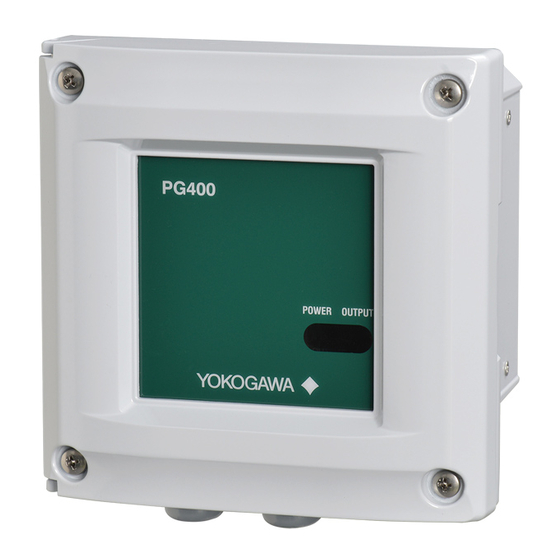
Thank you for purchasing the PG400 Pulse Generator for Clean Unit. This Instructor’s Manual contains all essential information for the user to make full use of PG400. Used in combination with an ultrasonic oscillator, the PG400 composes an ultrasonic cleaning device, supplying the operating power to the oscillator via cabling. -
Page 3: Safety Precautions
WARNING Installation and wiring The PG400 should only be used with equipment that meets the relevant IEC, American or Canadian standards. Yokogawa accepts no responsibility for the misuse of this unit. Don’t install “general purpose type” instruments in the hazardous area. -
Page 4: Compliant Standards
The product is provided on an “as is” basis. YOKOGAWA shall have neither liability nor responsibility to any person or entity with respect to any direct or indirect loss or damage arising from using the product or any defect of the product that YOKOGAWA can not predict in advance. Compliant Standards Safety: UL 61010-1 CAN/CSA-C22.2 No.61010-1... - Page 5 Information of the WEEE Directive This product is purposely designed to be used in a large scale fixed installations only and, therefore, is out of scope of the WEEE Directive. The WEEE Directive does not apply. This product should be disposed in accordance with local and national legislation/regulations. The WEEE Directive is only valid in the EU.
- Page 6 If damage is found, retain the original packing materials (including the outer box) and then immediately notify the carrier and the relevant Yokogawa sales office. Verify the items on the name plate including Model, Suffix code, affixed to the left side of the instrument, are correct and same as your order.
- Page 7 <PG400 Pulse Generator for Clean Unit> Accessories Name Q’ ty Remarks Cable gland 3 pieces 1 rubber plug is attached.(Part No. of the set K8008EN) Plate 1 piece For cable gland connection (Part No. K8008ET) Option Mounting bracket 1 set...
- Page 8 <PG400 Pulse Generator for Clean Unit> Dimensions Unit: mm 4-M6 depth 8 For power supply For Oscillator cable (not used) Conduit Adapter (Option code: /CB, /CD, /CF) Unit: mm(inch) Plate Case Packing Approx. 55(2.2") (1.93") G1/2 female thread (/CB) 1/2 NPT female thread (/CD) Adapter M20x1.5 (/CF)
- Page 9 <PG400 Pulse Generator for Clean Unit> (Note) The universal mounting kit (/UM) contains the pipe and wall mounting hardware (/U) and the panel mounting hardware (/PM). Panel mounting hardware (Option code: /PM, /UM) Unit: mm 2-M5 length 35 4-M6 * Spacing panel cutout *: Tighten the four screws to a torque of 2 N•m.
- Page 10 <PG400 Pulse Generator for Clean Unit> Wall mounting hardware (Option code: /U, /UM) Unit: mm 4-M6 * For wall mounting 3-ø10 holes *: Tighten the four screws to a torque of 2 N•m. Wall mounting hardware for replace (from PUS400G/TUS400G) (Option code: /U1)
-
Page 11: Installation And Wiring
This chapter describes wiring and installation. Installation The PG400 is weatherproof and can be installed both indoors and outdoors. It should, however, be installed as close as possible to the holders for pH meters or turbidity detectors. Avoid long cable runs of oscillator cables between the instrument and detectors. - Page 12 <PG400 Pulse Generator for Clean Unit> 2.2.1 Removing/Installation protect cover The protect cover (Part No. K8008EF) covers high-voltage power supply terminals and output terminals. WARNING To ensure your safety, before you remove the protect cover, be sure to shut down the power supply and wait for 15 seconds after LED light turns off.
-
Page 13: Wiring Power Supply
For power supply, wire cables with a flammability rating of UL 2556 VW-1 or equivalent. CAUTION Turn off power supply to PG400 before wiring. Power rating must comply with PG400 specification. Power voltage must match with the one indicated on the name plate. -
Page 14: Operation
For CSA compliance (Type: -AD), use ones with cross-section area of 0.75 mm to 2.1 mm CAUTION Connect PG400 to ground (Class D ground: 100 ohm or less) for interference avoidance and safety reasons. Use ground cables with larger cross - sectional area. Connect the ground cable to the internal/ external grounding terminal. -
Page 15: Maintenance
(1) Turn OFF the output switch of PG400. Then, feed a sample water into the turbidity detector or pH sensor at the same flow rate as in a steady-state operation. Actuate the turbidimeter or pH analyzer. -
Page 16: Revision Record
If the POWER LED stays off even after the fuse is replaced, contact Yokogawa service center. For replacement, use the fuse with a rating specified on page 7 the table “Option parts”.
Need help?
Do you have a question about the PG400 and is the answer not in the manual?
Questions and answers