Table of Contents
Advertisement
Quick Links
Advertisement
Table of Contents

Summary of Contents for INSIGHT STRIKE FINDER
- Page 1 www.insightavionics.com...
- Page 2 Drawing 2000-01 Revision 2.0 April, 1997...
-
Page 3: Table Of Contents
STRIKE FINDER DIGITAL WEATHER AVOIDANCE CONTENTS Page STRIKE FINDER DIGITAL WEATHER AVOIDANCE SYSTEM .....4 Cautionary Notice ................4 Warning ....................4 Warranty ..................... 4 Introduction ..................5 Functional Description ................ 5 Viewing The Display ................6 Bearing and Range ................6 Strike Finder System Components ............. - Page 4 Wind Shear ..................45 Tornado .................... 45 Hail ....................46 Airframe Icing ................... 46 WEATHER AVOIDANCE SYSTEMS ........... 47 Strike Finder System ................ 47 Strike Finder Advantages ..............47 Weather Radar ................. 48 Precipitation Rate Table ..............49 Radar Advantages ................49 Radar Disadvantages ...............
-
Page 5: Strike Finder Digital Weather Avoidance System
Although this relationship exists, it is neither precise nor 100% accurate. A wide avoidance path ensures that Strike Finder serves the cause of safety. No storm avoidance product today, Strike Finder included, is designed to enable, or encourage, penetration of convective buildups and/or thunderstorms. -
Page 6: Introduction
STRIKE FINDER DIGITAL WEATHER AVOIDANCE Introduction The Strike Finder Digital Weather Avoidance System detects and analyzes the electrical activity emanating from thunderstorms within a 200 nautical mile (nm) radius of the aircraft. A unique graphic display plots an accurate, reliable and easily-interpreted picture of electrical activity that you can use to circumnavigate the hazards associated with thunderstorms. -
Page 7: Viewing The Display
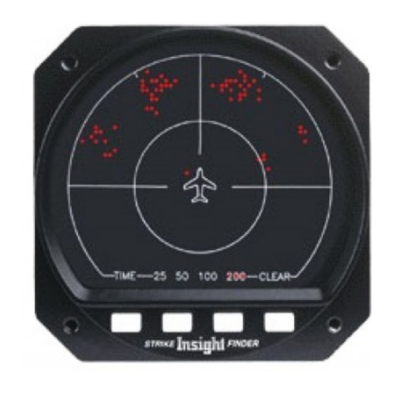
STRIKE FINDER DIGITAL WEATHER AVOIDANCE Viewing the Display The Strike Finder System analyzes the individual strike signal properties to determine the bearing, range and severity of the activity. Strike data plotted on the display as single orange dots by range and azimuth, in relation to the aircraft symbol (“heads up”). -
Page 8: Strike Finder System Components
STRIKE FINDER DIGITAL WEATHER AVOIDANCE Strike Finder System Components Strike Finder has two components: Figure 3 shows the Display and Sensor. These two components are connected with a shielded cable. Display Sensor Figure 3. System Components: Display and Sensor Display The Display mounts in the aircraft instrument panel. -
Page 9: Features & Functions
STRIKE FINDER DIGITAL WEATHER AVOIDANCE FEATURES AND FUNCTIONS 30˚Azimuth Marker Automatic Test Status Annunciator “Walking Dot” Outer Range Ring Strike Data Aircraft Symbol Half Range Ring Range Indicators Range Cursor Alphanumeric Indicator Clear Display Button Time Travel Button Zoom-In Button Zoom-Out Button Figure 4. -
Page 10: Operating Procedures
Clear Display Button — clears the display of all dots but does not erase the strike data history employed by the Time Travel function. OPERATING PROCEDURES Strike Finder is easy to use. Only four buttons control all of its functions pre-flight check because many features are automatic. Perform a... -
Page 11: Automatic Test Status Annunciator
STRIKE FINDER DIGITAL WEATHER AVOIDANCE On start-up Strike Finder automatically selects the 200 nm range view. This ensures that distant weather is depicted, and not inadvertently ignored with a shorter range selection. Automatic Test Status Annunciator Once the boot-up procedure is completed, the Strike Finder System automatically carries out a self-diagnostic system test every minute. -
Page 12: Zoom-In/Zoom-Out
Zoom Figure 6. Zoom Buttons Zoom-In/Zoom-Out Strike Finder is capable of 25, 50, 100 and 200 nm range views. The two Zoom- center buttons control display zoom (see Figure 6). Depressing the Zoom-In button increases the range setting. Depressing the button reduces the view of the display to the next shorter range. -
Page 13: Zoom Limits
STRIKE FINDER DIGITAL WEATHER AVOIDANCE Zoom Limits When Strike Finder is fully zoomed in to a 25 nm range view, the Zoom- Zoom Indicator. Similarly, button has no effect other than to display the Zoom out button has no affect on the display when 200 nm range view is already selected. -
Page 14: Clear Display
Time Travel erase any strike data history employed by the function, (see Figure 7). Strike Finder will immediately plot new lightning activity on the display. Evaluating Dot Accumulation Clearing the display at any time, also permits evaluating the rate of dot accumulation as an indicator of storm activity and severity. -
Page 15: Dealer Mode
STRIKE FINDER DIGITAL WEATHER AVOIDANCE Special Functions Dealer Mode Figure 8. Dealer Mode Buttons Installation or Service Procedure Dealer Mode function is used only by a qualified technician to verify correct operation during installation, or servicing (see Figure 8). Starting Dealer Mode... -
Page 16: System Reset
USING STRIKE FINDER Introduction Effective and safe use of Strike Finder as a weather avoidance technology is predicated on a knowledge of thunderstorms and their hazards. A mere understanding of the features and functions of Strike Finder is not enough to ensure safe piloting. -
Page 17: Course Selection
Display Interpretation Think of your Strike Finder as a 360˚ weather window, with a viewing distance of up to 200 nm from your aircraft. Lightning activity is illuminated on the Display as bright orange dots. -
Page 18: Long Range View
STRIKE FINDER DIGITAL WEATHER AVOIDANCE Long Range View In the 100 and 200 nm views, the Strike Finder system will plot one strike dot on the display for each lightning strike detected. If Strike Finder detects strike dots increased lightning activity in the same area, the number of... - Page 19 Zoomed to 50 or 25 nm transforms to sixteen strike dots. Figure 10-B. Cell Zoomed In strike dot Strike Finder plots a single in the 100 or 200 nm range view, depicting an area of 100 sq miles where lightning activity is detected.
-
Page 20: Display Zoom Interpretation
Zoom has on Figure 13 shows the Strike Finder display in the 200 nm range view. Three strike areas are plotted, a small cluster at 11:00, another at 1:00 and a single strike dot at 4:00. - Page 21 STRIKE FINDER DIGITAL WEATHER AVOIDANCE Figures 14-16 shows the display zoomed from 200 nm through to 25 nm range view.The viewable area is reduced by one-quarter each time the zoom buttons are depressed, resulting in less area being displayed. Range and...
-
Page 22: Caution And Danger Areas
25 nm Figure 17. CAUTION and DANGER Areas Note: these colored areas, as graphically shown, do not and will not appear on your Strike Finder.They are shown here to emphasize the importance of storm activity in these areas. PILOT’S GUIDE... - Page 23 (see Planning To Deviate, p. 27, for details). clear area free of Knowing how to interpret the display, for bearing, range and storm severity, is only part of the equation when using Strike Finder as an avoidance device. Heading and track must also be considered. PILOT’S...
-
Page 24: Effect Of Wind Drift
With Light or No Wind Figure 18, (p.324, shows the Strike Finder CAUTION and DANGER areas and the effect of a strong cross wind on a 200 kt aircraft. One active thunderstorm appears as a small cluster at 10:30 about 150 nm from the aircraft. -
Page 25: Assessing Storm Severity
How does one identify a severe storm? Is a single orange dot a storm? What does a real threat look like? The Strike Finder system shows the relative amount of lightning activity within the thunderstorm cells. Pay close attention to the strike accumulation rate as a location and severity indicator of storm activity. -
Page 26: Strike Dot Interpretation
4) Storm Persistence—Strike Finder strike dots have a persistence or dot longevity, of five minutes. For severe storms, dots remain in the same Clear location for much longer than five minutes. -
Page 27: Range Interpretation
Remember, in the 100 or 200 nm range Strike Finder will plot one visible dot per the square area depicted, no matter the number of actual strikes detected. -
Page 28: Planning To Deviate
Figure 20. Strike Dots Zoomed Through the Four Ranges Views Planning To Deviate If your Strike Finder detects thunderstorms close to your intended flight path, a deviation from your present course must be initiated. Observe the Strike Finder closely, to determine the distance and bearing of the thunderstorm from the aircraft. -
Page 29: One-Quarter Rule
Storms at the track, will have an avoidance distance of one quarter of the Display range. For example, Figure 22 shows the Strike Finder display in the 200 nm range view. Using this knowledge, in conjunction with the One-Quarter Rule, the distance at 30-degrees can be interpreted as being 50 nm or one-quarter of 200 nm, (see Table 2 for One-Quarter Rule distances and “required storm... -
Page 30: Rule-Of-Thumb
STRIKE FINDER DIGITAL WEATHER AVOIDANCE Table 2. One-Quarter Rule Table Rule-Of-Thumb avoid all storms in the 100 nm range view A good rule-of-thumb, is to 30-degrees. In addition, an extra 10-degrees is advisable for added safety. This range setting and angle will position the aircraft approximately 40 miles from the storm, thereby providing a better margin of safety. -
Page 31: Drift Near Frontal Thunderstorms
STRIKE FINDER DIGITAL WEATHER AVOIDANCE In the example shown in Figure 23-B, a 50 kt cross wind drifting the plane toward the storm, has decreased the avoidance distance or angle from 30-degrees to 16-degrees. The pilot should compensate for drift with additional crabbing (turning into the wind). -
Page 32: Estimating Distances Between Cells
STRIKE FINDER DIGITAL WEATHER AVOIDANCE Figure 24-A 200 nm Range View Figure 24-B 50 nm Range View Strike Dot Distance Using One-Quarter Rule Estimating Distances Between Cells Figure 25-A shows two cell formations in the 200 nm range view. The cells are calculated to be approximately 50 nm left and right from the projected track, or 100 nm apart. -
Page 33: Storm Examples
STRIKE FINDER DIGITAL WEATHER AVOIDANCE STORM EXAMPLES Study the following examples to become familiar with the Strike Finder display. Storm 1 Figure 26. Display set to 200 nm range view showing three storm cells Description At 200 nm range view, three areas of activity are shown.Cells... -
Page 34: Storm 2
STRIKE FINDER DIGITAL WEATHER AVOIDANCE Storm 2 Figure 27. Display set to 50 nm range view showing enhanced view of storm Description This display range is set to 50 nm. At this range view, a strike is depicted as a cluster of four dots. There is a linear cluster at 10 nm, 1:30 position. -
Page 35: Cell Stretch
Strike Finder should not exhibit significant cell stretch with every storm. If this occurs, suspect interference from another electronic device on-board the aircraft. (see Appendix A, Troubleshooting, p.51). -
Page 36: Cell Smear
Cell smear is the apparent elongation of a cell in the direction of aircraft movement. This effect is a result of the aircraft’s motion relative to the storm, and the persistence of dots plotted on the Strike Finder display. For example, Figure 29 shows the display depicting a cell at the 3:00 position. -
Page 37: Storm Avoidance Mapping
Strike Finder display to the storm maps. Long Range Detection Figure 30 shows the Strike Finder display depicting a line of five thunderstorms. Two large thunderstorms appear about 150 nm and 175 nm away from the aircraft at 10:30 and 9:30 position. A smaller storm appears about 100 nm at 9:30 position. - Page 38 DIGITAL WEATHER AVOIDANCE Progression of Flight Path Figure 31 (p.36), shows that the Strike Finder system has automatically updated the display as the aircraft has progressed on course. The cells to the left side of the aircraft appear closer, about 90 nm but present no threat based on present heading.
- Page 39 STRIKE FINDER DIGITAL WEATHER AVOIDANCE Zoomed to 50 nm Range View zoomed Figure 33 (p.37), shows the display 20 minutes later to the 50 nm range view. The distant thunderstorms are no longer visible. They have zoomed off the display. The two thunderstorms ahead appear larger and better defined.
-
Page 41: Weather Avoidance Concepts
STRIKE FINDER DIGITAL WEATHER AVOIDANCE Weather Avoidance Concepts The Strike Finder system reliably detects the electrical activity that is present in all thunderstorms, enabling you to avoid lightning, and all the hazards produced by thunderstorms. When the thunderstorm menace is embedded or hidden by clouds or poor visibility, Strike Finder provides an especially useful picture of the threat. -
Page 42: Thunderstorm Stages
STRIKE FINDER DIGITAL WEATHER AVOIDANCE Figure 35. Thunderstorm Development Thunderstorm Stages The life cycle of a thunderstorm includes three stages: cumulus, mature, and dissipating. Cumulus Stage — is the beginning of all thunderstorms. The size of the updraft region (cell) becomes larger and the cloud grows in an unsteady succession of upward bulges, as evident by the thermals that reach to the top. -
Page 43: Thunderstorm Types
STRIKE FINDER DIGITAL WEATHER AVOIDANCE Thunderstorm Types There are several types of thunderstorms: The air mass thunderstorm, the severe thunderstorm, and squall-line thunderstorm. An air mass cell thunderstorm consists of one and lasts less than one hour, whereas multicells or supercells, and lasts the severe thunderstorm is composed of for up to two hours. -
Page 44: Hazards Associated With Thunderstorms
STRIKE FINDER DIGITAL WEATHER AVOIDANCE Figure 36. Severe Thunderstorm HAZARDS WITH THUNDERSTORMS A thunderstorm contains every conceivable aerial hazard: lightning, catastrophic turbulence, wind shear, severe icing, destructive hail and tornadoes. Lightning Lightning is the visible electrical discharge produced by thunderstorms. The convective flow of air currents circulating up and down create friction... -
Page 45: Downburst
STRIKE FINDER DIGITAL WEATHER AVOIDANCE This is often oversimplified as positive charges at the upper reaches and negative at the base, (see Figure 37). Lightning takes place when the positive and negative charge has a voltage difference of about 300,000 volts per foot. Lightning strikes at the speed of light. -
Page 46: Wind Shear
STRIKE FINDER DIGITAL WEATHER AVOIDANCE Wind Shear Wind shear is the sudden “tearing” or “shearing” effect when there is a violent change of wind over a short distance. The change can occur in either speed or direction (horizontal and vertical), or both. Wind shear... -
Page 47: Hail
STRIKE FINDER DIGITAL WEATHER AVOIDANCE Hail Hail is precipitation that falls from thunderstorms as round or irregular balls of ice. The freezing process takes place when water droplets are continuously rotated up and down by air currents within the cell of a thunderstorm. -
Page 48: Weather Avoidance Systems
The information is depicted on the Strike Finder display as one cohesive picture of weather mapping. Strike Finder Advantages The Strike Finder system and its unique patented processing of lightning signals has some very important advantages over weather radar. -
Page 49: Weather Radar
STRIKE FINDER DIGITAL WEATHER AVOIDANCE Figure 40. Radar Suffering Attenuation Weather Radar The weather radar system sweeps a narrow and highly directional beam of energy, in a lateral arc of 90 or 120-degrees in front of the aircraft. A portion of the beam energy is reflected by the water droplets and returns to the antenna. -
Page 50: Precipitation Rate Table
For example, the Cumulus stage of a thunderstorm is usually rain free and therefore will not appear on weather radar. However, it generally contains lightning which will appear on the Strike Finder display screen, alerting the pilot to its severity and location. -
Page 51: Attenuation
Manual Detects All to Storm Height Tilt Controll Table 4. Strike Finder/Radar, Comparison Attenuation Attenuation is a non-obvious radar problem, created by the very process it uses to measure precipitation density. Moisture in close proximity to the aircraft will scatter the radar beam, thereby depleting the energy return to the radar receiver.The same effect is found with car headlights when driving... -
Page 52: Appendix
Strike Finder installation, in terms of electrical interference. Once the power is turned on, Strike Finder automatically carries out a self- diagnostic test every minute. If a fault is detected, the appropriate error code is displayed in the lower left corner of the display, and the test rate is “walking... - Page 53 STRIKE FINDER DIGITAL WEATHER AVOIDANCE Diagnostic Error Codes - Interpretation Figure 41. Diagnostic Codes X0, X1, or X2 - Continuously Displayed X channel bandwidth, gain, or phase error. Fault may be in display, sensor, or cable. Check sensor cable/connector wiring for conductors XA and XB.
- Page 54 Watch the activity number in the lower left corner.This number is a count of the number of times Strike Finder is triggered. The goal of interference investigation is to reduce the rate of triggering (in the absence of real storm activity) to one every 30 seconds, or longer, and to ensure that no dots are being plotted.
- Page 55 STRIKE FINDER DIGITAL WEATHER AVOIDANCE P - Continuously displayed sense antenna P channel failure, or fault. Check sensor cable / connector wiring for conductor PF. Exchange display and sensor with known good components. P - Intermittently displayed This code will disappear and re-appear, randomly. When a real storm cell is being plotted on the display, a ‘mirror image’, or ambiguous storm cell will...
- Page 56 Check sensor cable/connector wiring for conductors +8V, -8V, GND, and Exchange display and sensor with known good components. S - Continuous Separation failure in test pulse hardware. Return display to Insight for repair. B - Continuous Non-volatile memory failure. Return display to Insight for repair.
-
Page 57: Appendix B Factory Service Procedures
It is helpful to our technicians if you tape a business card or note to the Strike Finder so that you may be contacted to discuss the problem and solution. Once repaired, the unit will be returned to you 2nd day, with shipping prepaid if it is still under warranty. -
Page 58: Appendix C Technical Specifications
STRIKE FINDER DIGITAL WEATHER AVOIDANCE APPENDIX C Strike Finder Technical Specifications SIZE: COOLING: Display/Processor: Conduction 3.19” (8.10 cm) high STRIKE RANGES: 3.19” (8.10 cm) wide 25, 50, 100 & 200 nm 9.50” (24.13 cm) deep (connector STRIKE VIEW ANGLE: adds 1.90” (4.83 cm) 360˚... -
Page 59: Appendix D Relative Bearing Stabilizer (Rbs)
This is achieved without the Strike Finder having to be slaved to an on-board compass system —no aircraft compass system needed. The connected to Strike Finder is all that is required, (see Figure 42). - Page 60 STRIKE FINDER DIGITAL WEATHER AVOIDANCE Operation Upon system start-up or reboot, a five minute warm-up is needed to achieve full stabilization (note that action is completely locked out for the first minute after power-up). If the aircraft heading is changed during the five minute warm-up period, the strike dots may drift somewhat from...
-
Page 61: Appendix E Questions & Answers
Clear the Strike Finder display to evaluate storm intensity. See Display Interpretation section for details. [3] If I have selected the 25 nm range view, will Strike Finder be still gathering data at 200 nm? Yes, Strike Finder is always gathering and analyzing data out to 200... -
Page 62: Appendix F Helpful Insight
STRIKE FINDER DIGITAL WEATHER AVOIDANCE APPENDIX F Helpful Insight The following are excerpts from Avionics Magazine, August 1988, with permission from the publishers and author: Electrostatic Charging In Flight by: Jay D. Cline, Dayton-Granger, Inc. It is widely known that electrostatic charging of aircraft in flight generates radio frequency noise which disrupts navigation and communications. - Page 63 STRIKE FINDER DIGITAL WEATHER AVOIDANCE Aircraft Charging These effects occur as an airplane flies through freezing rain, ice crystals, dust, sand and snow. Contact with these particles leaves a positive or negative charge on the air frame. As the aircraft charge builds, a potential is reached where the charge leaks off the aircraft and antennas, generating broad band radio frequency noise.
- Page 64 STRIKE FINDER DIGITAL WEATHER AVOIDANCE The pilot is seldom aware of what happened. When communications are reestablished, ATC may assume the pilot was not paying attention to his radio. Solutions to corona noise include antennas that are insulated from space and static discharges positioned where the aircraft is most likely to go into corona;...
- Page 65 STRIKE FINDER DIGITAL WEATHER AVOIDANCE NOTES PILOT’S GUIDE...
- Page 66 Add Strike Finder’s optional Stabilization Module and you can enjoy the convenience of heading stabilization without having a slaved compass system. The Stabilization Module directs lightning strike information to automatically rotate on the display with your heading changes. As you alter course to avoid thunderstorms, Strike Finder depicts the weather relative to your current position.
Need help?
Do you have a question about the STRIKE FINDER and is the answer not in the manual?
Questions and answers