Table of Contents
Advertisement
Quick Links
Advertisement
Table of Contents

Related Manuals for REGLOPLAS 90smart

Summary of Contents for REGLOPLAS 90smart
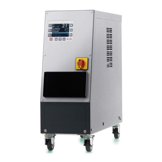
- Page 1 90smart/150smart Operating Instructions...
- Page 2 The contents, however, do not constitute a binding obligation on the part of Regloplas AG and are subject to change without notice. © Copyright 2013 Regloplas AG...
-
Page 3: Table Of Contents
Setting the Set-point values ..............13 Parameter Menu ..................14 RT70 Control System - Functions ................. 14 Powering Up..................... 14 Shutdown ....................14 Leak-stop operation ................. 14 Emptying (option) ..................15 Contents i Temperature Control Unit 90smart/150smart... - Page 4 Block diagram 90smart ..................25 Block diagram 150smart ..................26 Graph (pump capacity) ..................27 Graph (Cooling capacity 90smart) ................ 28 Graph (Cooling capacity 150smart) ..............28 Components/Spare parts 90smart ............... 29 Components/Spare parts 150smart ..............32 ...
-
Page 5: General Safety Information
Failure to heed the information can result in property damage as well as minor or moderate personal injury! NOTE Denotes general information, useful advice to users and work recommenda- tions, which, however, do not have any influence on the safety and health of personnel. General Safety Information 1 Temperature Control Unit 90smart/150smart... -
Page 6: Range Of Application
Safety Information General information The Regloplas temperature control unit is safe to operate but can cause danger if it is used incorrectly or for a purpose other than its intended use. It should be noted that any such incorrect use or non-compliance... -
Page 7: Information For Operators And Personnel
If the temperature control unit is damaged, it must not remain in use; the defective part must be replaced or repaired immediately. Only original Regloplas replacement parts may be used. Damage due to the use of third-party parts renders any and all warranty claims null and void. -
Page 8: Using This Documentation
The corresponding additional documents are included with special versions of devices. Any additional documents sup- plement and/or replace the descriptions contained in this documentation, which are then either invalid or only conditionally valid. 4 General Safety Information Temperature Control Unit 90smart/150smart... -
Page 9: Operating Instructions
Operating Range The operating range and heat transfer fluid of the Temperature Control Unit 90smart/150smart are shown in the following table (in this regard, see also the chapter "Technical Data" in the Maintenance section). Temperature Control 90smart... -
Page 10: Start-Up
The Operating Instructions for the temperature control unit must be kept at all times close at hand for the personnel responsible for start-up and operation. Please ensure that the operating instructions are read. By do- 6 Operating Instructions Temperature Control Unit 90smart/150smart... -
Page 11: Inspection Of Consumers
Descaling can be carried out using the Regloplas REG de- scaling unit (see the "Regloplas Temperature Control Technolo- gy" brochure, REG data sheet) -
Page 12: Electrical Connections
The vent valves on the consumer and the shut-off valves (if present) must be open. RT34 Control System RT34 Control System - front panel 8 Operating Instructions Temperature Control Unit 90smart/150smart... -
Page 13: Powering Up
A. Cool down device and switch off, turn switch to position - and switch device on again. Turn switch to position A and hold down until fully drained (observe maximum expansion volume!) Operating Instructions 9 Temperature Control Unit 90smart/150smart... -
Page 14: Displays
Before detaching connecting lines from the temperature control circuit, first al- low the temperature control unit to cool down, as a function of the outlet tem- perature, and then switch it off! Check that the pump is no longer running! 10 Operating Instructions Temperature Control Unit 90smart/150smart... -
Page 15: Malfunctions
Automatic water filling does not switch off. Possible causes: Float switch defective Device Solenoid valve water filling (Y2) defective or dirty overfilled Leak in cooler Clean or replace defective parts Operating Instructions 11 Temperature Control Unit 90smart/150smart... -
Page 16: Rt70 Control System
Scrolling through pages Setting the additional display Setting the parameters Selection of the device functions (toggling Alarm reset and alarm history SP1/SP2, drainage by suction, leak-stop) Button ON/OFF Enter key Navigation upward Navigation downward 12 Operating Instructions Temperature Control Unit 90smart/150smart... -
Page 17: Status Leds
Setting the Set-point values The set-point values SP1 and SP2 are set by pressing the key F1. The set-point value is then coloured light blue and can be set with the RCD Operating Instructions 13 Temperature Control Unit 90smart/150smart... -
Page 18: Parameter Menu
OFF appears on the display. Leak-stop operation The leak-stop operation is activated by pressing the F3 key and selecting the leak-stop symbol and is only possible if it is supported by the device type. 14 Operating Instructions Temperature Control Unit 90smart/150smart... -
Page 19: Emptying (Option)
The suction or blowing out program can be aborted by pressing the ON/OFF button. When the ON/OFF button is pressed again (wait until the display reads OFF), the unit switches back to normal operation. Operating Instructions 15 Temperature Control Unit 90smart/150smart... -
Page 20: Operation With Code/Password
User password - Default 0000 (switched off) Technician password - Default 0070 Service password - only for personnel trained by Regloplas NOTE It is strongly recommended that an operator password should be set up when commissioning the temperature control unit. -
Page 21: Alarm Messages
Attention - temperature control cabinet too high ambient temperature Check the outlet pressure (min. 0.7 bar must be pre- Flow switch act sent) Max. temperature exceeded Max. temperature of the heat transfer medium may Operating Instructions 17 Temperature Control Unit 90smart/150smart... -
Page 22: System Errors/System Notes
(e.g., 2000 hours, see the RT70 control system programming instructions). Please note that the instructions below are based on a daily operating time of 8 hours. In multi-shift operation, the inspections and maintenance 18 Operating Instructions Temperature Control Unit 90smart/150smart... - Page 23 Descale cooler - exercise caution when tightening the screwed connections on the heat exchanger (max. 170 Nm). Check pump capacity (the flow rate and final pressure must comply with the pump characteristic) Operating Instructions 19 Temperature Control Unit 90smart/150smart...
-
Page 24: Cleaning
Allow the temperature control unit to cool down and, if necessary, drain it be- fore any repair! Switch off the temperature control unit: press the main switch and unplug from the mains! Disconnect all hose couplings from the temperature control unit! 20 Operating Instructions Temperature Control Unit 90smart/150smart... -
Page 25: Transport
Disposal The temperature control unit must be drained completely and disposed of in accordance with local regulations. The temperature control unit can also be returned to Regloplas AG, Swit- zerland, for disposal. Operating Instructions 21 Temperature Control Unit 90smart/150smart... - Page 26 V 11/2014 22 Operating Instructions Temperature Control Unit 90smart/150smart...
-
Page 27: Maintenance
Important - twisting of the When attach- hoses can also be ing/detaching a hose, al- caused during installa- ways hold it in place with tion. a second wrench Maintenance 23 Temperature Control Unit 90smart/150smart... -
Page 28: Technical Data 90Smart/150Smart
Dimensions W/H/D 202/560/661 mm 202/560/661 mm Weight approx. 44 kg approx. 50 kg Colour RAL 9006/7016 RAL 9006/7016 Ambient temperature max. 40°C max. 40°C Continuous sound pressure level < 70 dB(A) < 70 dB(A) 24 Maintenance Temperature Control Unit 90smart/150smart... -
Page 29: Block Diagram 90Smart
Vessel, reservoir, tank Safety thermostat Cooler Pump Bypass Level control Filter - cooling circuit Solenoid valve - auto. water refill Consumer Solenoid valve - cooling Temperature probe - internal Solenoid valve - suction (optional) Heating Maintenance 25 Temperature Control Unit 90smart/150smart... -
Page 30: Block Diagram 150Smart
Vessel, reservoir, tank Safety thermostat Cooler Pump Filter - cooling circuit Level control Consumer Solenoid valve - auto. water refill Temperature probe - internal Solenoid valve - cooling Heating Solenoid valve - suction (optional) 26 Maintenance Temperature Control Unit 90smart/150smart... -
Page 31: Graph (Pump Capacity)
V 11/2014 Graph (pump capacity) 1 - Pump curve TP20 2 - Pump curve TS22, TS22H Pump capacity - Delivery rate V as a function of pressure (p), bypass not tak- en into account Maintenance 27 Temperature Control Unit 90smart/150smart... -
Page 32: Graph (Cooling Capacity 90Smart)
V 11/2014 Graph (Cooling capacity 90smart) 1 - Cooling curve 90smart (1K) 2 - Cooling curve 90smart (2K) Cooling capacity (P) as a function of out- let temperature ( ) Cooling water temperature 20 °C Flow rate 20 l/min Graph (Cooling capacity 150smart) -
Page 33: Components/Spare Parts 90Smart
V 11/2014 Components/Spare parts 90smart V21a Maintenance 29 Temperature Control Unit 90smart/150smart... - Page 34 V 11/2014 S3/B1 30 Maintenance Temperature Control Unit 90smart/150smart...
- Page 35 See electrical wiring diagram of the temperature control unit for additional elec- trical components! CAUTION Only authentic (OEM) Regloplas spare parts may be used! In case of damage from the use of non-OEM parts, the warranty will be rendered null and void! Maintenance ...
-
Page 36: Components/Spare Parts 150Smart
V 11/2014 Components/Spare parts 150smart V21a 32 Maintenance Temperature Control Unit 90smart/150smart... - Page 37 V 11/2014 S3/B1 Maintenance 33 Temperature Control Unit 90smart/150smart...
- Page 38 See electrical wiring diagram of the temperature control unit for additional elec- trical components! CAUTION Only authentic (OEM) Regloplas spare parts may be used! In case of damage from the use of non-OEM parts, the warranty will be rendered null and void! 34 ...
-
Page 39: Dimension Sheet 90Smart
V 11/2014 Dimension sheet 90smart Item Designation Item Designation RT70 Control System Inlet Main switch Cooling water IN Cooling water OUT Outlet Maintenance 35 Temperature Control Unit 90smart/150smart... -
Page 40: Dimension Sheet 150Smart
V 11/2014 Dimension sheet 150smart Item Designation Item Designation RT70 Control System Inlet Main switch Cooling water IN Cooling water OUT Outlet 36 Maintenance Temperature Control Unit 90smart/150smart... - Page 41 V 11/2014 Maintenance 37 Temperature Control Unit 90smart/150smart...
Need help?
Do you have a question about the 90smart and is the answer not in the manual?
Questions and answers
Vad betyder detta larm?.
The REGLOPLAS 90smart alarm indicates a fault or abnormal condition in the system. When an alarm occurs:
- The Alarm Reset button can be pressed to acknowledge and clear the alarm.
- If no active alarm is present, pressing the button shows the last ten alarm messages with date and time.
- Specific alarms and their meanings include:
- “Service is due”: Perform maintenance and increment "Next Maintenance" by 1000 hours.
- “Deviation set-point value/outlet underrun” or “exceeded”: Adjust the outlet temperature and acknowledge.
- “Leak stop not possible/allowed”: Reduce temperature or the unit does not support leak stop.
- “Suction not possible”: Switch to normal operation mode.
- “Level 1 underrun”: Refill heat transfer medium.
Each alarm requires specific action to resolve the issue and restore proper operation.
This answer is automatically generated