Advertisement
Quick Links
L
D
T
ittfinski
aten
echnik
Operating Instruction
feedback module
with integrated
8-fold occupancy detectors
for the RS-feedback bus
from the Digital-Professional-Series !
RS-8-G
>> finished module in a case <<
⇒
monitors up to 8 different track sections
(current detection from 0,001[1mA] up to 3 ampere)
⇒
integrated voltage control
(avoiding "track free" feedback in case of power failures)
⇒
separated by opto coupler
(between track- power supply voltage and feedback bus)
⇒
compatible to RS-feedback bus)
(can be operated together with RS-16-O, LR101, LS100 etc.)
⇒
suitable for digital control:
Digital Plus from Lenz.
This product is not a toy! Not suitable for children under 14 years of age! The kit
contains small parts, which should be kept away from children under 3! Improper
use will imply danger of injuring due to sharp edges and tips! Please store this
instruction carefully.
Multi-Digital
Introduction / Safety Information:
You have purchased the 8-fold feedback module RS-8 with
integrated detection of track occupancy for your model railway.
The RS-8 is a high quality product that is supplied within the
assortment of Littfinski DatenTechnik (LDT).
We wish you having a good time using this product.
Our products are either available as kits or as finished modules.
The finished modules come with 24 month warranty.
• Please read the following instructions carefully. Warranty will
expire due to damages caused by disregarding the operating
instruction. LDT will also be not liable for any consequential
damages caused by improper use or installation.
Connection of the RS-8 with your digital model
railway:
• Attention: Please switch off your digital control unit and
unplug the transformers from AC-current before starting
connecting the unit.
• Power Supply: Connect the feedback module at the 4-
poles clamp with your model train transformer (14 to 18V
AC). It is also possible to connect the RS-8 module directly
to the digital circuit. In this case connect both clamps of
KL7 to clamp J and K of a power booster (LZV100 / LV101
/ LV102 / LV200).
Feedback bus: Connect the input R and S at the 4-pole
clamp to the identically marked clamps of the command
station LZ100 or LZV100. Further feedback modules (RS-8,
RS-16-O, LR101, LS100 etc.) have to be simply connected
in parallel.
Digital Current: Connect the clamps J and K at IN1 and IN2
of the 20-pole clamp with the identically marked clamps on
the power booster LZV100 / LV101 / LV102 / LV200).
(LDT)
300213
Part-No.:
General Functions:
The feedback module RS-8 combines the occupied track
detection and the feedback function. The 8 detectors for
occupied tracks work by detection of current. In cases a
connected track is occupied by an object with a minimum of
0,001 Ampere (1mA) consuming current, the track will be
detected as occupied.
Locomotive decoder, coach lights or resistance axles are
consuming electrical power and therefore induce the detection
of an occupied track.
Digital-Profi werden!
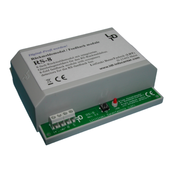
Rückmeldemodul / Feedback module
RS-8
8-fach Rückmeldemodul mit integrierten Gleisbelegtmeldern
für den RS-Rückmeldebus.
8-fold feedback module with occupancy detectors for
RS-feedback bus.
KL7
KL8
RS-8
Rev. 3.2
R S
14 ..18V~
Littfinski DatenTechnik (LDT)
The max. track current per output shall not exceed 3
Ampere. A peak current of up to 7 Ampere is acceptable. The
supply booster has to identify the overload or short circuit
and has to switch off.
The track voltage (digital current circuit), the power supply and
the feedback bus are separated by opto galvanic.
The current for the tracks can therefore safely be supplied from
different transformers without having a negative effect on the
power booster (LZV100 / LV101 / LV102 / LV200).
The modular concept of occupied track detectors and
feedback decoders implements a considerable problem: As
soon as there is no electrical power on the tracks, all tracks are
detected as free because no consuming current is detected.
There are track occupied detectors available on the market which
use an auxiliary voltage to solve this problem, but this can
influence
sometimes
the
disturbances and is therefore no suitable solution.
As the feedback module RS-8 has a build-in intelligence
(microprocessor Z86... [IC1], we have integrated a solution called
voltage-monitor. In case of voltage drop or short circuit there is
no inaccurate "free track" detection reported back via the
feedback bus to the digital control unit or the PC. All track
occupancies will be "frozen" during this phase of voltage
interruption.
As soon as there is current on the tracks again the actual
situations on the tracks will be detected and reported back via
the feedback bus.
The feedback modules RS-8 are suitable for decentralize
installation underneath the model railway installation. There are
4-bores on the edges of the modules for quick and easy
installation.
The modules are connected with each other's via the RS-
feedback bus (cables to the connecting clamps R and S).
Therefore each feedback module gets it's own individual address
which is unique and cannot be allocated a second time by
another module.
Littfinski DatenTechnik (LDT)
www.ldt-infocenter.com
8-fach Rückmeldemodul
mit Gleisbesetztmeldern
8-fold feedback module
with occupancy detectors
S1
LED1
locomotive
decoder
causing
Advertisement

Related Manuals for Littfinski Daten Technik RS-8


Summary of Contents for Littfinski Daten Technik RS-8
- Page 1 (LZV100 / LV101 / LV102 / LV200). The RS-8 is a high quality product that is supplied within the assortment of Littfinski DatenTechnik (LDT). The modular concept of occupied track detectors and We wish you having a good time using this product.
- Page 2 For assembling 2 different power booster (LZV100 / LV101 / Please test the detecting function of the modules first before LV102 / LV200) the RS-8 is divided into 2 x 4 track occupancy connecting it to the tracks. controller. The output 1 to 4 gets the supply via the input To do this you can use a resistor (several of hundred Ohms) or a clamps IN1 and the output 5 to 8 via IN2.
Need help?
Do you have a question about the RS-8 and is the answer not in the manual?
Questions and answers