Table of Contents
Advertisement
Quick Links
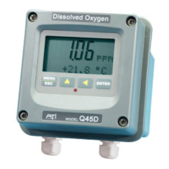
Model Q45D
Optical D.O. Monitor
(Q45D SOFTWARE VERSIONS 4.02 AND HIGHER)
Home Office
Analytical Technology, Inc.
6 Iron Bridge Drive
Collegeville, PA 19426
Ph:(800) 959-0299
(610) 917-0991
Fax: (610) 917-0992
Email: sales@analyticaltechnology.com
Auto-Clean
System
ATI (UK) Limited
Unit 1 & 2 Gatehead Business Park
Delph New Road, Delph
Saddleworth OL3 5DE
Ph: 0800-018-4020
Fax: + 44 (0) 1457-874-468
Email:sales@atiuk.com
European Office
+ 44 (0) 1457-873-318
Advertisement
Table of Contents

Related Manuals for Analytical Technology Q45D


Summary of Contents for Analytical Technology Q45D
- Page 1 Model Q45D Auto-Clean Optical D.O. Monitor System (Q45D SOFTWARE VERSIONS 4.02 AND HIGHER) Home Office European Office Analytical Technology, Inc. ATI (UK) Limited 6 Iron Bridge Drive Unit 1 & 2 Gatehead Business Park Collegeville, PA 19426 Delph New Road, Delph...
- Page 2 PRODUCT WARRANTY Analytical Technology, Inc. (Manufacturer) warrants to the Customer that if any part(s) of the Manufacturer's products proves to be defective in materials or workmanship within the earlier of 18 months of the date of shipment or 12 months of the date of start-up, such defective parts will be repaired or replaced free of charge.
-
Page 3: Table Of Contents
6.4 Dissolved oxygen Zero Cal ......45 1.4 Q45D/60D Optical Auto-Clean System 6.5 Temperature Calibration ......47 Specifications ............7 1.5 Q45D Performance Specifications ....8 Part 7 – Sensor Cleaning System ......48 7.1 General ............48 Part 2 – Mechanical Installation ....... 9 ... - Page 4 Figure 13 - Alarm Relay Example ................... 36 Figure 14 - Cleaner Failure & Jumper Map Config ............50 Figure 15 - Q45D ISA (Ideal) PID Equation ..............52 Figure 16 - Q45D Display Messages ................60 Figure 17 - Pt1000 RTD Table ..................62 ...
-
Page 5: Part 1 - Introduction
0-40.0 ppm and the sensing system will operate on water streams with temperatures from 0 to 50°C. The Q45D monitor is designed to use either a galvanic membrane sensor or an optical oxygen sensor. While the sensor technology is different for each type, the basic monitoring system remains the same. -
Page 6: Features
Q45D Optical Auto-Clean D.O. Monitor Part 1 - Introduction Once installed and placed into operation, the Auto-Clean system will provide months of reliable D.O. measurement in almost any application. Sensors should be checked for build-up after the first 3 months to verify that the cleaner is keeping the optical element clean. - Page 7 Q45D Optical Auto-Clean D.O. Monitor Part 1 - Introduction - Large, high contrast, custom Super-Twist display with LED backlight provides excellent readability even in low light conditions. A secondary line of display utilizes 5x7 dot matrix characters for clear message display. Two measured parameters may be on the display simultaneously.
-
Page 8: Figure 1 - D.o. System W/Auto-Clean Sensor
Q45D Optical Auto-Clean D.O. Monitor Part 1 - Introduction Series Q45 Auto-Clean Monitor Figure 1 - D.O. System w/Auto-Clean Sensor O&M Manual Rev-E (1/11) -
Page 9: Q45D/60D Optical Auto-Clean System Specifications
Q45D Optical Auto-Clean D.O. Monitor Part 1 - Introduction 1.4 Q45D/60D Optical Auto-Clean System Specifications Displayed Parameters Main input, 0.00 to 40.00 ppm or mg/L. %Saturation, 0 to 999% Sensor temperature, 0 to 50.0 °C (32 to 122 ºF) Sensor Signal -40 to +2000 mVDC... -
Page 10: Q45D Performance Specifications
Q45D Optical Auto-Clean D.O. Monitor Part 1 - Introduction Temperature Input Pt1000 RTD for automatic compensation Sensor Optical oxygen sensor with replaceable sensing element. Optical element life 3-5 years. Sensor Materials Sensor Cable 30 ft. (10 meter) cable. Max sensor-transmitter distance 100 feet (30 meters) with j-box. -
Page 11: Part 2 - Mechanical Installation
Part 2 – Mechanical Installation 2.1 General The Q45D Auto-Clean Monitor is housed in a Nema 4X (IP- 65) enclosure. The monitor must be mounted near the measurement point, with a maximum of 60 feet between the monitor and the sensor. The standard system is supplied with a 30 ft. -
Page 12: Figure 2 - Monitor Assembly Wall Mount Dim
Q45D/60 Optical Auto-Clean D.O. Monitor Part 2 – Mechanical Installation Series Q45 Auto-Clean Monitor Figure 2 - Monitor Assembly Wall Mount Dim. O&M Manual Rev-E (1/11) -
Page 13: Railing Mount
Q45D/60 Optical Auto-Clean D.O. Monitor Part 2 – Mechanical Installation 2.3 Railing Mount Figure 3 shows the mounting assembly used to mount the electronic monitor to a typical safety handrail that surrounds many aeration tanks. This bracket assembly consists of vertical channels attached to the handrail with u-bolts. -
Page 14: Figure 4 - Submersible Sensor Mounting Assembly
Q45D/60 Optical Auto-Clean D.O. Monitor Part 2 – Mechanical Installation Figure 4 - Submersible Sensor Mounting Assembly O&M Manual Rev-E (1/11) -
Page 15: Figure 5 - Mounting Assembly Detail
Q45D/60 Optical Auto-Clean D.O. Monitor Part 2 – Mechanical Installation Figure 5 - Mounting Assembly Detail O&M Manual Rev-E (1/11) -
Page 16: Part 3 - Electrical Installation
Part 3 – Electrical Installation 3.1 General Q45D Auto-Clean D.O. monitors are powered from either 115 or 230 VAC, 50/60 Hz. Monitors can draw up to 3 amps when the internal air compressor activates as part of the sensor cleaning system. Normal current draw is less than 0.2 amps when the cleaner is off. -
Page 17: Figure 6 - D.o. Monitor Electrical Connections
Q45D Optical Auto-Clean D.O. Monitor Part 4 – Optical D.O. Sensor Figure 6 - D.O. Monitor Electrical Connections WIRING NOTE: The cable for the optical D.O. sensor contains a “black” wire that is actually a black shrink tube covering both a blue and a pink wire. -
Page 18: Relay Wiring
If the cable length is changed, do not strip these two wires. 3.3 Relay Wiring Relay wiring is done to terminal blocks inside the Q45D display assembly. This unit actually contains two SPDT relays, but one of the relays is used to control the activation of the sensor automatic cleaning system. -
Page 19: Part 4 - Optical D.o. Sensor
Part 4 – Optical D.O. Sensor 4.1 General Optical D.O. sensors are supplied complete and ready to use. All that’s needed is to make the proper sensor connections as shown in the previous section. A rubber boot protects the end of the sensor in transit. Leave the protective boot in place until the sensor is to be placed into operation. -
Page 20: Optical Sensing
D.O. concentration on the sensor side of the film than on the bulk solution side. The automatic air cleaning system integrated into the Q45D system will eliminate coating problems by cleaning the sensor on a regular programmed schedule. -
Page 21: Part 5 - Operation
Part 5 – Operation 5.1 User Interface The user interface for the Q45 Series instrument consists of a custom display and a membrane keypad. All functions are accessed from this user interface (no internal jumpers, pots, etc.). RELAY 4-DIGIT INDICATOR MAIN DISPLAY MENU ICONS MENU ICONS... -
Page 22: Keys
Q45D Optical Auto-Clean D.O. Monitor Part 5 – Operation 5.11 Keys All user configurations occur through the use of four membrane keys. These keys are used as follows: • MENU/ESC To scroll through the menu section headers or to escape from anywhere in software. - Page 23 Q45D Optical Auto-Clean D.O. Monitor Part 5 – Operation Lower Line During normal operation, the lower line of the display indicates user-selected secondary measurements that the system is making. This also includes calibration data from the last calibration sequence and the transmitter model number and software version.
-
Page 24: Software
B icon indicates that the battery voltage is at a low level. The battery power option and the relay option cannot be installed together. 5.2 Software The software of the Q45D is organized in an easy to follow menu-based system. All user settings are organized under four menu... - Page 25 Q45D Optical Auto-Clean D.O. Monitor Part 5 – Operation Each list item allows a change to a stored system variable. List items are designed in one of two forms: simple single variable, or multiple variable sequences. In the single variable format, the user can quickly modify one parameter - for example, changing temperature display units from °F to...
-
Page 26: Figure 11 - Software Map
Q45D Optical Auto-Clean D.O. Monitor Part 5 – Operation Start MENU MEASURE CONFIG CONTROL DIAG SECTIONS (display only) *PID 0% #1 Temperature Cal D.O. Entry Lock Set Hold Sensor mV *PID 100% #1 Cal Temp Set Delay Fault List *PID Setpoint #1... - Page 27 Q45D Optical Auto-Clean D.O. Monitor Part 5 – Operation To select a list item for modification, first select the proper menu with the MENU key. Scroll to the list item with the UP arrow key and then press the ENTER key. This tells the system that the user wishes to perform a change on that item.
-
Page 28: Measure Menu [Measure]
Q45D Optical Auto-Clean D.O. Monitor Part 5 – Operation 5.22 Measure Menu [MEASURE] The default menu for the system is the display-only menu MEASURE. This menu is a display-only measurement menu, and has no changeable list items. When left alone, the instrument will automatically return to this menu after approximately 30 minutes. -
Page 29: Calibration Menu [Cal]
Q45D Optical Auto-Clean D.O. Monitor Part 5 – Operation % Saturation The most common display of D.O. in water is either PPM or mg/L units. However, the same PPM value at different water temperatures can represent quite different concentrations of oxygen in terms of the percent of saturation. - Page 30 Q45D Optical Auto-Clean D.O. Monitor Part 5 – Operation 5.24 Configuration Menu [CONFIG] The Configuration Menu contains all of the general user settings: Entry Lock This function allows the user to lock out unauthorized tampering with instrument settings. All settings may be viewed while the instrument is locked, but they cannot be modified.
- Page 31 Press ENTER to store the new value. Zero Filter The Q45D allows the user to program a value near zero below which the monitor will read zero. Because sensors rarely have a perfect zero stability, this zero filter eliminates occasional displays of numbers that are not meaningful.
- Page 32 Q45D Optical Auto-Clean D.O. Monitor Part 5 – Operation Proc Cond The Q45D instrument also utilizes the process conductivity value as an input for the calculation of a theoretical ppm value during a saturation calibration. This value is only required to be entered during initial installation - it does not need to be modified at every calibration.
-
Page 33: Control Menu [Control]
Q45D Optical Auto-Clean D.O. Monitor Part 5 – Operation indications to other remote devices. The AL setting allows two setpoints to be selected for the same relay, producing a HI-LO alarm band. In this mode, Relay A will trip inside or outside of the band, depending upon the Phase selected. - Page 34 Q45D Optical Auto-Clean D.O. Monitor Part 5 – Operation Set PID 0% Set PID 100% [Out1=PID] If the PID is enabled, this function sets the minimum and maximum controller end points. Unlike the standard 4-20 mA output, the controller does not “scale”...
- Page 35 Q45D Optical Auto-Clean D.O. Monitor Part 5 – Operation PID Int [Out1=PID] Integral is the number of “repeats-per-minute” of the action of the controller. It is the number of times per minute that the controller acts on the input error. At a setting of 2.0 rpm, there are two repeats every minute.
- Page 36 Q45D Optical Auto-Clean D.O. Monitor Part 5 – Operation A Setpoint This function establishes the dissolved oxygen trip point for relay A. The entry value is limited to a value within the range of 0 to 40.00 ppm. Use the LEFT arrow key to select the first digit to be modified.
-
Page 37: Figure 12 - Control Relay Example
Q45D Optical Auto-Clean D.O. Monitor Part 5 – Operation See Figure 12 below for a visual description of a typical control relay application. When value rises to ≥ 1.000 ppm, relay When value rises to ≥ 1.050 ppm, When value falls to ≤ 0.950 ppm, relay When value falls to ≤... -
Page 38: Figure 13 - Alarm Relay Example
Q45D Optical Auto-Clean D.O. Monitor Part 5 – Operation Figure 13 is a visual description of a typical alarm relay application. When value rises to ≥ 1.000 ppm, When value falls to < 1.000 ppm, relay relay closes, until value falls back to <... - Page 39 Q45D Optical Auto-Clean D.O. Monitor Part 5 – Operation The timer HOLD setting allows an output hold time to be entered into the cleaning cycle. This hold time allows the outputs to stabilize back to normal readings before the outputs are released from their “hold” state.
-
Page 40: Diagnostics Menu [Diag]
Q45D Optical Auto-Clean D.O. Monitor Part 5 – Operation If the B mode selection is changed while the sensor wash timer is in mid-cycle (and the HOLD is enabled), the HOLD must be turned off manually to return all of the outputs to normal operation. - Page 41 Q45D Optical Auto-Clean D.O. Monitor Part 5 – Operation high number of internal tests occurring. As faults are corrected, they are immediately cleared. Faults are not stored; therefore, they are immediately removed if power is cycled. If the problem causing...
- Page 42 Q45D Optical Auto-Clean D.O. Monitor Part 5 – Operation PID Timer This function sets a timer to monitor the amount of time the PID controller remains at 0% or 100%. This function only appears if the PID controller is enabled.
- Page 43 Q45D Optical Auto-Clean D.O. Monitor Part 5 – Operation modify desired value; selections are between 4mA, and 20mA. Press ENTER to store the new value. Fail Out #2 This function sets the fail-mode of current loop output #2 under a FAIL condition.
-
Page 44: Part 6 - Calibration
The output of the optical dissolved oxygen sensor will degrade very slowly over the lifetime of the optical element, which is normally 3-5 years. To account for this degradation, the Q45D system should be re-calibrated about every 6 months. The frequency of calibration must be determined by the application. - Page 45 Q45D Optical Auto-Clean D.O. Monitor Part 6 – Calibration 1. Determine whether the calibration will be done on-line or with the sensor removed and placed into a bucket of clean water. If the sensor is removed from the application, rinse and clean if necessary.
-
Page 46: Dissolved Oxygen Span Air Cal (%-Sat)
Q45D Optical Auto-Clean D.O. Monitor Part 6 – Calibration 6.3 Dissolved Oxygen Span Air Cal (%-sat) This is the recommended method for air temperatures greater than about 5 C; however, it requires that the sensor be removed from the process and cleaned. Once cleaned, the sensor is held in air and allowed time to adjust to the air temperature. -
Page 47: Dissolved Oxygen Zero Cal
Q45D Optical Auto-Clean D.O. Monitor Part 6 – Calibration 7. The system now begins acquiring data for the calibration value. As data is gathered, the units for ppm and temperature may flash. Flashing units indicate that this parameter is unstable. - Page 48 Q45D Optical Auto-Clean D.O. Monitor Part 6 – Calibration 2. Place about an 3 inches of zero solution in a container large enough to immerse the end of the sensor. You can make a zero solution by adding about 2 teaspoons of powdered sodium sulfite to up to 1 gallon of water.
-
Page 49: Temperature Calibration
Q45D Optical Auto-Clean D.O. Monitor Part 6 – Calibration 6.5 Temperature Calibration Calibration of the temperature circuit is rarely ever required. The temperature calibration sequence is essentially a 1-point offset calibration that allows adjustments of approximately ±5 °C. The sensor temperature may be calibrated on line, or the sensor can be removed from the process and placed into a known solution temperature reference. -
Page 50: Part 7 - Sensor Cleaning System
Part 7 – Sensor Cleaning System 7.1 General The cleaner control system located in the D.O. system enclosure contains a number of components designed to supply pulses of high pressure air to the tip of the sensor. The main components and their function are as follows: Compressor: The air compressor is a small AC powered... -
Page 51: Cleaner Sequence
You will hear the compressor activate. 7.3 Cleaner Malfunction Alarm (Optional) The Q45D/60 can be supplied with an optional Clean Failure Detection alarm to indicate that the sensor cleaner system has failed to operate properly. This alarm circuit will indicate a failure condition if the Auto-Clean system fails to activate during a 24 hour period. -
Page 52: Figure 14 - Cleaner Failure & Jumper Map Config
Q45D Optical Auto-Clean D.O. Monitor Part 8 – PID Controller The relay associated with this alarm is a SPST relay that can be configured with a jumper to operate either as a normally open (NO) or normally closed (NC) contact. The jumper is located inside the protective circuit cover in the terminal compartment of the monitor. -
Page 53: Part 8 - Pid Controller Details
Q45D Optical Auto-Clean D.O. Monitor Part 8 – PID Controller Part 8 – PID Controller Details 8.1 PID Description PID control, like many other control schemes, are used in chemical control to improve the efficiency of chemical addition or control. By... -
Page 54: Figure 15 - Q45D Isa (Ideal) Pid Equation
= controller error (e=measured variable – setpoint) Figure 15 - Q45D ISA (Ideal) PID Equation The most notable feature of the algorithm is the fact the proportional gain term affects all components directly (unlike some other algorithms - like the “series” form.) If a pre-existing controller... - Page 55 ½ of the oscillatory value, and the I term is increased to give the desired response. This can be done with the Q45D controller, with the exception that the I term should start no lower than 1.0.
-
Page 56: Classical Pid Tuning
Q45D Optical Auto-Clean D.O. Monitor Part 8 – PID Controller 8.3 Classical PID Tuning Unlike many high speed position applications where PID loops are commonly used, the chemical feed application employed by this instrument does not require intense mathematical exercise to determine tuning parameters for the PID. - Page 57 Q45D Optical Auto-Clean D.O. Monitor Part 8 – PID Controller Closed-loop control can only be effective if all elements in the loop are properly selected for the application, and the process behavior is properly understood. Luckily, the nature of simple chemical control process are generally slow in nature.
-
Page 58: Part 9 - System Maintenance
Part 9 – System Maintenance 9.1 General The Q45D/60 Dissolved oxygen System will generally provide unattended operation over long periods of time. With proper care, the system should continue to provide measurements indefinitely. For reliable operation, maintenance on the system must be done on a regular schedule. -
Page 59: Part 10 - Troubleshooting
Part 10 – Troubleshooting 10.1 General The information included in this section is intended to be used in an attempt to quickly resolve an operational problem with the system. During any troubleshooting process, it will save the most time if the operator can first determine if the problem is related to the analyzer, sensor, or some external source. -
Page 60: Analyzer Tests
Q45D/60 Dissolved Oxygen System Part 10– Troubleshooting 5. If rigid conduit has been run directly to the Q45D enclosure, check for signs that moisture has followed conduit into the enclosure. 6. Check for ground loops. Although the sensor is electrically isolated from the process water, high frequency sources of electrical noise may still cause erratic behavior in extreme conditions. -
Page 61: Display Messages
Q45D/60 Dissolved Oxygen System Part 10– Troubleshooting 3. Using a DVM, check the voltage across the BLUE and WHITE wires coming from the power supply board in the base of the enclosure. FIRST, disconnect any wiring going to I-out#1. Then, verify voltage across these wires is about 16-18 VDC when still connected to the terminal strip on the front half of the enclosure. -
Page 62: Figure 16 - Q45D Display Messages
Temp Low The temperature reading is < -10 ºC Same as “Temp High” above. TC Error TC may be open or shorted. Check sensor wiring and perform RTD test as described in sensor manual. Check j-box connections. Figure 16 - Q45D Display Messages O&M Manual Rev-E (1/11) -
Page 63: Sensor Tests
Q45D/60 Dissolved Oxygen System Part 10– Troubleshooting MESSAGE DESCRIPTION POSSIBLE CORRECTION D.O. Cal Fail Failure of oxygen calibration. FAIL Clean sensor redo span icon will extinguish until calibration. If still failure, sensor successful calibration been slope may be less than 20% or performed, or 30 minutes passes greater than 500%. -
Page 64: Figure 17 - Pt1000 Rtd Table
Q45D/60 Dissolved Oxygen System Part 10– Troubleshooting 2. Prior to disconnecting the sensor, measure the sensor output voltage at the analyzer terminal strip with a DVM while the sensor is hanging in air. If the sensor has been connected to a powered analyzer for at... -
Page 65: Figure 18 - Reference - Barometric Pressure Conversion
Q45D/60 Dissolved Oxygen System Part 10– Troubleshooting Barometric Pressure Conversion Inches of Millimeters of Feet Above Mercury(inHg) Mercury (mmHg) Sea Level 22.00 558.8 +8790 22.50 571.5 +8053 23.00 584.2 +7347 23.50 596.9 +6671 24.00 609.6 +6023 24.50 622.3 +5402 25.00 635.0... -
Page 66: Figure 19 - Reference - Oxygen Solubility Table
Q45D/60 Dissolved Oxygen System Part 10– Troubleshooting Oxygen Solubility vs. Temperature Temperature Temperature °F °C °F °C 14.6 23.3 14.1 24.4 13.7 25.6 13.3 26.7 12.9 27.8 12.6 28.9 12.2 30.0 11.9 31.1 11.6 32.2 10.0 11.3 33.3 11.1 11.0 34.4... -
Page 67: Spare Parts
Spare Parts PART NO. DESCRIPTION 03-0337 Front Lid electronics assembly 07-0011 D.O. Display Assembly, 115 VAC 07-0030 D.O. Display Assembly, 230 VAC 01-0242 Power supply assembly (specify 115 or 230 VAC) 01-0317 Universal Autoclean PCB Assy 63-0100 Submersible D.O. Sensor with 30’ cable 36-0040 Compression Pump, 12VDC 36-0041...
Need help?
Do you have a question about the Q45D and is the answer not in the manual?
Questions and answers