Table of Contents
Advertisement
Quick Links
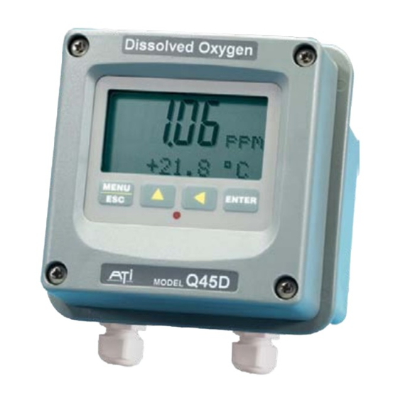
Model Q45D/60
Optical D.O. Monitor
(Q45D SOFTWARE VERSIONS 4.02 AND HIGHER)
Home Office
Analytical Technology, Inc.
6 Iron Bridge Drive
Collegeville, PA 19426
Ph: (800) 959-0299
(610) 917-0991
Fax: (610) 917-0992
Email: sales@analyticaltechnology.com
System
European Office
Analytical Technology
Bank Chambers, 33 Stamford St.
Mossley, Ashton-u-Lyne OL50LL
Ph:
+ 44 (0) 1457 832800
Fax:
+ 44 (0) 1457 839500
Email: sales@atiuk.com
0800-018-4020
Advertisement
Table of Contents

Related Manuals for Analytical Technology Q45D/60


Summary of Contents for Analytical Technology Q45D/60
- Page 1 Model Q45D/60 Optical D.O. Monitor System (Q45D SOFTWARE VERSIONS 4.02 AND HIGHER) Home Office European Office Analytical Technology, Inc. Analytical Technology 6 Iron Bridge Drive Bank Chambers, 33 Stamford St. Collegeville, PA 19426 Mossley, Ashton-u-Lyne OL50LL Ph: (800) 959-0299 0800-018-4020...
- Page 2 PRODUCT WARRANTY Analytical Technology, Inc. (Manufacturer) warrants to the Customer that if any part(s) of the Manufacturer's products proves to be defective in materials or workmanship within the earlier of 18 months of the date of shipment or 12 months of the date of start- up, such defective parts will be repaired or replaced free of charge.
-
Page 3: Table Of Contents
PART 1 - INTRODUCTION ..........................4 General ..............................4 Standard System ............................. 4 Features ..............................4 Q45D/60 System Specifications ......................6 Q45D Performance Specifications ......................8 PART 2 – ANALYZER MOUNTING ......................... 9 General ..............................9 Figure 2-1 Q45 Enclosure Dimensions, AC Powered Units (ATI-0706) ............10 Figure 2-2 Q45 Enclosure Dimensions, 2-Wire and Battery Units (ATI-0655) .......... - Page 4 5.25 Control Menu [CONTROL] ......................... 38 Figure 5-3 Control Relay Example, Hysteresis and Two Opposite Phase Options ........41 Figure 5-4 Alarm Relay Example ....................... 42 5.26 Diagnostics Menu [DIAG] ........................43 PART 6 – CALIBRATION ..........................47 6.1 General ..............................47 6.11 D.O.
-
Page 5: Part 1 - Introduction
Features • Standard Q45D/60 electronic transmitters are designed to be a fully isolated, loop powered instruments for 2-wire DC applications. Optional integral power supply card for 115/230 VAC operation, and optional battery power supply card for portable datalogging applications are available. - Page 6 Q45D-ODO Optical D.O. System Part 1 – Introduction • AC power option provides dual SPDT relay operation and one additional isolated analog output. Software settings for relay control include setpoint, deadband, phase, delay, and failsafe. Software controls automatically appear in menu list when hardware option card is plugged in and system power is applied.
-
Page 7: Q45D/60 System Specifications
Q45D-ODO Optical D.O. System Part 1 – Introduction Q45D/60 System Specifications (Common to all variations) Displayed Parameters Main input, 0.1 ppm to 40.0 ppm %Saturation, 0 to 999.9% Sensor temperature, -10.0 to 50.0°C (23 to 122ºF) Sensor signal, -40 to +2000 mVDC Loop current, 4.00 to 20.00 mA... - Page 8 Q45D-ODO Optical D.O. System Part 1 – Introduction Sensor Optical oxygen sensor utilizing fluorescence quenching technology. Optical element life 3-5 years. Sensor Materials Noryl, PVC, and stainless steel Sensor Cable Submersible: 30 ft. (9.1 m) Max. Sensor-to-Analyzer Distance 100 feet (30 m), with junction box (NOT common to all variations) Standard 2-Wire (Loop-powered) Transmitter: Power...
-
Page 9: Q45D Performance Specifications
Q45D-ODO Optical D.O. System Part 1 – Introduction Analog Outputs Two 4-20 mA outputs. Output one programmable for PPM oxygen or PID. Output 2 programmable for PPM or mg/L oxygen, % saturation, or Temperature. Max load 550 Ohms for each output. Outputs ground isolated and isolated from each other. -
Page 10: Part 2 - Analyzer Mounting
Part 2 – Analyzer Mounting General All Q45 Series instruments offer maximum mounting flexibility. A bracket is included with each unit that allows mounting to walls or pipes. In all cases, choose a location that is readily accessible for calibrations. Also consider that it may be necessary to utilize a location where solutions can be used during the calibration process. - Page 11 Q45D-ODO Optical D.O.System Part 2– Analyzer Mounting Figure 2-1 Q45 Enclosure Dimensions, AC Powered Units (ATI-0706) O & M Manual Revision C (7/09) 10 -...
- Page 12 Q45D-ODO Optical D.O.System Part 2– Analyzer Mounting Figure 2-2 Q45 Enclosure Dimensions, 2-Wire and Battery Units (ATI-0655) O & M Manual Revision C (7/09) 11 -...
-
Page 13: Wall Or Pipe Mount
Q45D-ODO Optical D.O.System Part 2– Analyzer Mounting Wall or Pipe Mount A PVC mounting bracket with attachment screws is supplied with each transmitter (see Figure 2-3 for dimensions). The multi-purpose bracket is attached to the rear of the enclosure using the four flat head screws. instrument is then attached to the wall using the four outer mounting holes in the bracket. - Page 14 Q45D-ODO Optical D.O.System Part 2– Analyzer Mounting M E N U E N T E R E S C Figure 2-4 Wall Mounting Diagram (ATI-0709) M E N U E N T E R E S C Figure 2-5 Pipe Mounting Diagram (ATI-0710 O &...
-
Page 15: Panel Mount, Ac Powered Monitor
Q45D-ODO Optical D.O.System Part 2– Analyzer Mounting Panel Mount, AC Powered Monitor Panel mounting of an AC powered monitor uses the panel mounting flange molded into the rear section of the enclosure. Figure 2-7 provides dimensions for the panel cutout required for mounting. The panel mounting bracket kit must be ordered separately (part number 05- 0068). -
Page 16: Part 3 - Optical D.o. Sensor
Part 3 – Optical D.O. Sensor 3.1 General Optical D.O. sensors are supplied complete and ready to use. All that’s needed is to make the proper sensor connections as shown in the previous section. A rubber boot protects the end of the sensor in transit. Leave the protective boot in place until the sensor is to be placed into operation. -
Page 17: Optical Sensing
Q45D-ODO Optical D.O. System Part 3– Optical D.O. Sensor 3.2 Optical Sensing Optical D.O. measurement employs technique called “fluorescence quenching” in order to measure molecular oxygen. The sensor will respond to oxygen either in the air or dissolved in water. A polymer element at the end of the sensor contains an embedded fluorescent dye. -
Page 18: Submersion Mounting
Q45D-ODO Optical D.O. System Part 3– Optical D.O. Sensor Submersion Mounting Most applications for D.O. monitoring are done using a submersible sensor. Optical oxygen sensor can be used in stagnant water conditions, as they do not need sample flow for measurement. Most aeration tank applications in wastewater treatment plants can for biologically active coatings on the face of the sensor, resulting in low readings. - Page 19 Q45D-ODO Optical D.O. System Part 3– Optical D.O. Sensor Flexible Air Line applicable for Auto-Clean Option Only! Figure 3-4 Mounting Assembly Detail (ATI-0873) O & M Manual Revision C (7/09) 18 -...
-
Page 20: Part 4 - Electrical Installation
Part 4 – Electrical Installation General The Q45 is powered in one of two ways, depending on the version purchased. The 2-wire version is a 16-35 VDC powered transmitter. The integral 115/230 VAC version requires line power. Please verify the type of unit before connecting any power. - Page 21 Q45D-ODO Optical D.O. System Part 4– Electrical Installation Figure 4-1 Loop-Power & Sensor Connections (ATI-0874) Notes: 1. Voltage between Terminals 7 and 8 MUST be between 16 and 35 VDC. 2. Earth ground into Terminal 12 is HIGHLY recommended. This connection can greatly improve stability in electrically noisy environments.
-
Page 22: Load Drive
Q45D-ODO Optical D.O. System Part 4– Electrical Installation 4.21 Load Drive The amount of resistance that the analog output can drive in the 115/230 VAC version is fixed. However, in the two-wire configuration, the load-drive level is dependent on the DC supply voltage provided to the controller. The two-wire instrument can operate on a power supply voltage of between 16 and 35 VDC. - Page 23 Q45D-ODO Optical D.O. System Part 4– Electrical Installation AC powered Q45 systems are supplied with 3 cable gland fittings and two ½” conduit adapters. One of the cable glands has a larger hole in the rubber gland and should be used for the power cord entry if a flexible power cord will be used for installation.
- Page 24 Q45D-ODO Optical D.O. System Part 4– Electrical Installation Figure 4-2 Line Power Connection (ATI-0761) The power strip, TB5, allows up to 12 AWG wire. A wire gauge of 16 AWG is recommended to allow for an easy pass-through into the M16 ports when wiring.
-
Page 25: Sensor Wiring
Q45D-ODO Optical D.O. System Part 4– Electrical Installation Two sets of SPDT relay contacts are provided on the power supply board. None of the relay contacts are powered. The user must supply the proper power to the contacts. For applications that require the same switched operating voltage as the Q45 (115 or 230 V), power may be jumpered from the power input terminals at TB5. -
Page 26: Junction Box Connection
Q45D-ODO Optical D.O. System Part 4– Electrical Installation Junction Box Connection For installations where the sensor is to be located more than 25 feet from the monitor (max. 100 feet), a junction box must be used. The junction box is shown in Figure 4-5, and is supplied with a ½"... -
Page 27: Part 5 - Configuration
Part 5 – Configuration User Interface The user interface for the Q45 Series instrument consists of a custom display and a membrane keypad. All functions are accessed from this user interface (no internal jumpers, pots, etc.). When power is first applied, you may notice that the display does not come on immediately. -
Page 28: Keys
Q45D/60 Dissolved Oxygen System Part 5 – Configuration 5.11 Keys All user configurations occur through the use of four membrane keys. These keys are used as follows: MENU/ESC To scroll through the menu section headers or to escape from anywhere in software. The escape sequence allows the user to back out of any changes in a logical manner. - Page 29 Q45D/60 Dissolved Oxygen System Part 5 – Configuration Lower Line During normal operation, the lower line of the display indicates user-selected secondary measurements that the system is making. This also includes calibration data from the last calibration sequence and the transmitter model number and software version.
-
Page 30: Software
Q45D/60 Dissolved Oxygen System Part 5 – Configuration Relay Area A/B The relay area contains two icons that indicate the state of the system relays (if the relay card is installed). If the battery board is installed instead, the B icon indicates that the battery voltage is at a low level. - Page 31 Q45D/60 Dissolved Oxygen System Part 5 – Configuration Any data that may be changed will be flashing. This flashing indicates user entry mode and is initiated by pressing the ENTER key. The UP arrow key will increase a flashing digit from 0 to 9. The LEFT arrow key moves the flashing digit from right to left.
- Page 32 Q45D/60 Dissolved Oxygen System Part 5 – Configuration Start MENU MEASURE CONFIG CONTROL DIAG SECTIONS (display only) *PID 0% #1 Temperature Cal D.O. Entry Lock Set Hold *PID 100% #1 Sensor mV Cal Temp Set Delay Fault List *PID Setpoint #1...
-
Page 33: Measure Menu [Measure]
Q45D/60 Dissolved Oxygen System Part 5 – Configuration 5.22 Measure Menu [MEASURE] The default menu for the system is the display-only menu MEASURE. This menu is a display-only measurement menu, and has no changeable list items. When left alone, the instrument will automatically return to this menu after approximately 30 minutes. -
Page 34: Calibration Menu [Cal]
Q45D/60 Dissolved Oxygen System Part 5 – Configuration % Saturation The most common display of D.O. in water is either PPM or mg/L units. However, the same PPM value at different water temperatures can represent quite different concentrations of oxygen in terms of the percent of saturation. This display simply indicates the % of oxygen saturation represented by the current PPM or mg/L display. -
Page 35: Configuration Menu [Config]
Q45D/60 Dissolved Oxygen System Part 5 – Configuration 5.24 Configuration Menu [CONFIG] The Configuration Menu contains all of the general user settings: Entry Lock This function allows the user to lock out unauthorized tampering with instrument settings. All settings may be viewed while the instrument is locked, but they cannot be modified. - Page 36 Q45D/60 Dissolved Oxygen System Part 5 – Configuration close to the same. However, programming for type 3 percent saturation changes the measured parameter to read a dissolved oxygen value that represents the percent of oxygen saturation at a given temperature. When this unit of measurement is selected, the main analog output and all alarm and control functions will relate to this measurement.
- Page 37 Q45D/60 Dissolved Oxygen System Part 5 – Configuration Note: If the user will not be changing solution conductivity dramatically during the calibration process, leave a default setting of 00.50 mS/cm. For ultrapure water applications, set this value to 0.00. For sea water applications, set this value to 53.00.
- Page 38 Q45D/60 Dissolved Oxygen System Part 5 – Configuration AC OPERATED UNITS ONLY *Relay B Mode Relay B can be used in a number of ways: as a setpoint control, as an alarm, or as the control logic for an automatic sensor cleaning system.
-
Page 39: Control Menu [Control]
Q45D/60 Dissolved Oxygen System Part 5 – Configuration 5.25 Control Menu [CONTROL] The Control Menu contains all of the output control user settings: Set 4 mA Set 20 mA [Iout1=D.O.] These functions set the main 4 and 20 mA current loop output points for the transmitter. - Page 40 Q45D/60 Dissolved Oxygen System Part 5 – Configuration use the UP and LEFT arrow keys to select the desired numerical value. Press ENTER to store the new value. PID Setpnt [Iout1=PID] The measured value which the controller is attempting to maintain by adjusting output value.
- Page 41 Q45D/60 Dissolved Oxygen System Part 5 – Configuration The entry value is limited to a value between 0 and 50 °C if it is set for temperature, within the range specified in “Set Range” if the output is set to track oxygen. The 4 mA and the 20 mA point must be at least 20 units away from each other.
- Page 42 Q45D/60 Dissolved Oxygen System Part 5 – Configuration When the phase is LO, the relay energizes and the LCD indicator illuminates when the oxygen level drops below the setpoint. The failsafe setting does have an impact on this logic. The description here assumes the failsafe setting is OFF.
- Page 43 Q45D/60 Dissolved Oxygen System Part 5 – Configuration If Relay A Mode is set to Alarm Mode, AL, then the following *Setpnt A-HI settings will appear in the Config Menu list automatically. In *Hyst A-HI this mode, two setpoints can be selected on the same relay, *Delay A-HI to create an alarm band.
-
Page 44: Diagnostics Menu [Diag]
Q45D/60 Dissolved Oxygen System Part 5 – Configuration 5.26 Diagnostics Menu [DIAG] The diagnostics menu contains all of the user settings that are specific to the system diagnostic functions, as well as functions that aid in troubleshooting application problems. Set Hold The Set Hold function locks the current loop output values on the present process value. - Page 45 Q45D/60 Dissolved Oxygen System Part 5 – Configuration which the diagnostic system re-detects them. exception to this rule is the calibration failure. When a calibration fails, no corrupt data is stored. Therefore, the system continues to function normally on the data that was present before the calibration was attempted.
- Page 46 Q45D/60 Dissolved Oxygen System Part 5 – Configuration Fail Out This function enables the user to define a specified value that the main current output will go to under fault conditions. When the Relay Option Board is installed, the display will read Fail Out #1.
- Page 47 Q45D/60 Dissolved Oxygen System Part 5 – Configuration When failsafe is selected to be ON, the normally-open contacts of the relay will be closed during normal operation. In an attempt to make this configuration less confusing, the LCD icon logic is reversed with this setting, and the icon is OFF under this normal condition.
-
Page 48: Part 6 - Calibration
Part 6 – Calibration 6.1 General The instrument must be calibrated periodically to maintain a high degree of measurement accuracy. A complete calibration will include zeroing and spanning the sensor. It is generally unnecessary to set the zero at every calibration, but it should be done during the initial installation. - Page 49 Q45D-ODO Optical D.O. System Part 6 –Calibration 2. If the sensor has been removed and placed into a bucket of water, allow sensor to temperature equilibrate with the solution as much as possible. With the sensor coming from an application which differs greatly in temperature, the user may have to wait as much as 20 minutes.
-
Page 50: Dissolved Oxygen Air Span Cal (% Sat)
Q45D-ODO Optical D.O. System Part 6 –Calibration 6.12 Dissolved Oxygen Air Span Cal (% sat) This is the recommended method for air temperatures greater than about 10C; however, it requires that the sensor be removed from the process and cleaned. Once cleaned, the sensor is held in air and allowed time to adjust to the air temperature. -
Page 51: Dissolved Oxygen Zero Cal
Q45D-ODO Optical D.O. System Part 6 –Calibration The system now begins acquiring data for the calibration value. As data is gathered, the units for ppm and temperature may flash. Flashing units indicate that this parameter is unstable. 8. The calibration data point acquisition will stop only when the data remains stable for a pre-determined amount of time (approximately 15- 20 seconds.) This can be overridden by pressing ENTER. - Page 52 Q45D-ODO Optical D.O. System Part 6 –Calibration 4. Press the ENTER key. The screen will display a flashing 1-spl for 1- point, a %-sat for Saturation air calibration, or a 3-zer for zero calibration. Using the UP arrow key, set for a 3-Zer zero calibration and press ENTER.
-
Page 53: Temperature Calibration
Q45D-ODO Optical D.O. System Part 6 –Calibration Temperature Calibration The temperature calibration sequence is essentially a 1-point offset calibration that allows adjustments of approximately ±5 °C. The sensor temperature may be calibrated on line, or the sensor can be removed from the process and placed into a known solution temperature reference. -
Page 54: Part 7 - Pid Controller Details
Part 7 – PID Controller Details PID Description PID control, like many other control schemes, are used in chemical control to improve the efficiency of chemical addition or control. By properly tuning the control loop that controls chemical addition, only the amount of chemical that is truly required is added to the system, saving money. - Page 55 Q45D-ODO Optical D.O. System Part 7 –PID Controller ∫ output Where: output = controller output proportional gain integral gain derivative gain time e(t) = controller error (e=measured variable – setpoint) Figure 7-1 Q45 ISA (Ideal) PID Equation The most notable feature of the algorithm is the fact the proportional gain term affects all components directly (unlike some other algorithms - like the “series”...
-
Page 56: Classical Pid Tuning
Q45D-ODO Optical D.O. System Part 7 –PID Controller Derivative gain. The addition of derivative control can be problematic in many applications, because it greatly contributes to oscillatory behavior. In inherently slow chemical control process’, differential control is generally added in very small amounts to suppress erratic actions in the process that are non-continuous, such as pumps and valves clicking on and off. -
Page 57: Manual Pid Override Control
Q45D-ODO Optical D.O. System Part 7 –PID Controller Manual PID Override Control The Q45 electronics is equipped designed to allow the user to take manual control of the PID output. This is often useful when starting up a control loop, or in the event that you wish to bump the system manually to measure system response time. - Page 58 Q45D-ODO Optical D.O. System Part 7 –PID Controller The easiest process’ to control with closed-loop schemes are generally linear, and symmetrical, in nature. For example, controlling level in tank where the opening of valve for a fixed period of time corresponds linearly to the amount that flows into a tank.
-
Page 59: Part 8 - System Maintenance
Part 8 – System Maintenance General The Q45D/60 Dissolved Oxygen System will generally provide unattended operation over long periods of time. With proper care, the system should continue to provide measurements indefinitely. For reliable operation, maintenance on the system must be done on a regular schedule. Keep in mind that preventive maintenance on a regular schedule is much less troublesome than emergency maintenance that always seems to come at the wrong time. -
Page 60: Part 9 - Troubleshooting
Part 9 – Troubleshooting General The information included in this section is intended to be used in an attempt to quickly resolve an operational problem with the system. During any troubleshooting process, it will save the most time if the operator can first determine if the problem is related to the analyzer, sensor, or some external source. -
Page 61: Analyzer Tests
Q45D-ODO Optical D.O. System Part 9– Troubleshooting 6. Check for ground loops. Although the sensor is electrically isolated from the process water, high frequency sources of electrical noise may still cause erratic behavior in extreme conditions. If readings are very erratic after wiring has been checked, check for a possible AC ground loop by temporarily placing the sensor into a bucket of water. -
Page 62: Display Messages
Q45D-ODO Optical D.O. System Part 9– Troubleshooting 3. Using a DVM, check the voltage across the BLUE and WHITE wires coming from the power supply board in the base of the enclosure. FIRST, disconnect any wiring going to Iout#1. Then, verify voltage across these wires is about 16-18 VDC when still connected to the terminal strip on the front half of the enclosure. - Page 63 Q45D-ODO Optical D.O. System Part 9– Troubleshooting MESSAGE DESCRIPTION POSSIBLE CORRECTION ≤ Max is 200 Entry failed, maximum user value allowed is 200. Reduce value to ≥ Min is 200 Entry failed, minimum value allowed is 200. Increase value to Cal Unstable Calibration problem, data too unstable to Clean sensor, get fresh cal solutions, allow...
-
Page 64: Sensor Tests
Q45D-ODO Optical D.O. System Part 9– Troubleshooting MESSAGE DESCRIPTION POSSIBLE CORRECTION D.O. Cal Fail Failure of oxygen calibration. FAIL icon will Clean sensor redo zero and span calibration. not extinguish until successful calibration If still failure, sensor slope may be less than has been performed, or 30 minutes passes 20% or greater than 500%. - Page 65 Q45D-ODO Optical D.O. System Part 9– Troubleshooting 3. Disconnect the five sensor wires from the oxygen monitor. Those wires are color coded red, white, blue, green, brown, and black. Connect the DVM between the brown and black wires. These are the RTD leads, and you should find a resistance value that depends on the temperature.
- Page 66 Q45D-ODO Optical D.O. System Part 9– Troubleshooting Barometric Pressure Conversion Inches of Millimeters of Feet Above Mercury(inHg) Mercury (mmHg) Sea Level 22.00 558.8 +8790 22.50 571.5 +8053 23.00 584.2 +7347 23.50 596.9 +6671 24.00 609.6 +6023 24.50 622.3 +5402 25.00 635.0 +4806 25.50...
- Page 67 Q45D-ODO Optical D.O. System Part 9– Troubleshooting Oxygen Solubility vs. Temperature Temperature Temperature °F °C °F °C 14.6 23.3 14.1 24.4 13.7 25.6 13.3 26.7 12.9 27.8 12.6 28.9 12.2 30.0 11.9 31.1 11.6 32.2 10.0 11.3 33.3 11.1 11.0 34.4 12.2 10.7...
-
Page 68: Spare Parts
Spare Parts Model Q45D Optical D.O. System Part No. Description 03-0337 Front Lid electronics assembly 07-0011 AC Powered monitor electronics assembly, 115 VAC 07-0011 AC Powered monitor electronics assembly, 230 VAC 63-0100 Submersible O.D.O. Sensor with 30’ cable 01-0242 Power supply circuit board assembly (specify 115 or 230 VAC) 07-0100 Junction box 31-0038...
Need help?
Do you have a question about the Q45D/60 and is the answer not in the manual?
Questions and answers