Table of Contents
Advertisement
Quick Links
Advertisement
Table of Contents

Related Manuals for Delta Electronics CMC-DN01


Summary of Contents for Delta Electronics CMC-DN01
- Page 1 CMC-DN01 DeviceNet Slave Communication Card Operation Manual 2011-12-26-A...
-
Page 3: Table Of Contents
Warning This operation manual provides introduction on the functions, specifications, installation, basic operation and settings for CMC-DN01 and the network protocol. This is an OPEN TYPE device and therefore should be installed in an enclosure free of airborne dust, humidity, electric shock and vibration. The enclosure should prevent non-maintenance staff from operating the device (e.g. - Page 4 DeviceNet Slave Communication Card CMC-DN01 Class 0x02 – Message router objects ....................20 Class 0x03 – DeviceNet objects......................21 Class 0x05 – Connection objects ....................... 21 Class 0x96 – Parameter objects......................22 Class 0x95 – DataConf........................23 DVP-PLC Operation Manual...
-
Page 5: Introduction To Cmc-Dn01
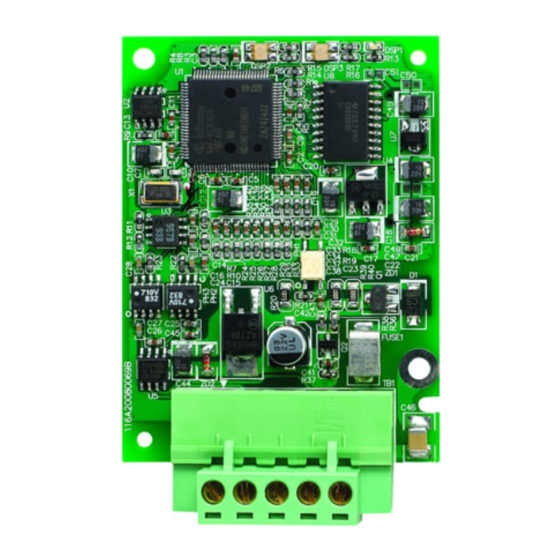
DeviceNet Slave Communication Card CMC-DN01 Introduction to CMC-DN01 1. Thank you for choosing Delta CMC-DN01 communication card. To ensure correct installation and operation of the product, please read this operation manual carefully before using it. 2. CMC-DN01 is the DeviceNet communication card able to conduct remote setups and communications through the DeviceNet bus. -
Page 6: Product Profile And Outline
DeviceNet Slave Communication Card CMC-DN01 Shock/vibration International standards: IEC 61800-5-1, IEC 60068-2-6/IEC 61800-5-1, resistance IEC 60068-2-27 Electrical Specifications Power supply voltage 5 VDC (supplied by AC motor drive) Insulation voltage 500 VDC Communication wire 0.85 W power consumption Power consumption... -
Page 7: Basic Operation
Press the pin to clip the holes with the PCB (Figure 1). 4. Screw up after the PCB is clipped with the holes (Figure 2). [Figure 1] [Figure 2] ⑦ Connect to the DeviceNet port: Insert the DeviceNet connector to the DeviceNet port on CMC-DN01 (Figure 3). DVP-PLC Operation Manual... -
Page 8: Vfd-C2000 Series Ac Motor Drive And Devicenet Master
DeviceNet Slave Communication Card CMC-DN01 [Figure 3] Constructing a DeviceNet network (Figure 4) The DVPDNET-SL module is the DeviceNet master. CMC-DN01 and the VFD-C2000 series AC motor drive construct the DeviceNet slave. Use the software DeviceNet Builder to configure the DeviceNet network. -
Page 9: Data Exchange In Devicenet
The VFD-C2000 series AC motor drive is connected to the DeviceNet network through CMC-DN01. Once CMC-DN01 receives the I/O data outputted from the DeviceNet master, it will next send these data to parameters in the AC motor drive. The parameters in the AC motor drive to receive these data are determined by the mapping relation set in CMC-DN01, and the setup is done by using the DeviceNet Builder software. -
Page 10: Establishing I/O Connection
(converted from the hex 2101), “Data_in[2]” to “8451” (converted from the hex 2103), “Data_out[1]” to “8192” (converted from the hex 2000” and “Data_out[2]” to “8193” (converted from the hex 2001). After the setup is completed, download the new mappings to CMC-DN01. Figure 4.2.1: Input data mapping Figure 4.2.2: Output data mapping... -
Page 11: Constructing A Devicenet Network
DVP-SV. Figure 4.3.1 Constructing a DeviceNet Network In this chapter, we will explain how to configure the VFD- C2000 series AC motor drive by an example. Constructing a DeviceNet Network through CMC-DN01 1. The DeviceNet Network Structure DVP-PLC Operation Manual... - Page 12 DeviceNet Slave Communication Card CMC-DN01 Figure 5.1.1: A constructed DeviceNet network 2. Setting DVPDNET-SL and VFD-C2000 series AC motor drive: Module Node address Baud rate DVPDNET-SL 500 kbps VFD-C2000 series AC motor drive 500 kbps Note: Setting the node address and baud rate of VFD-C2000 series AC motor drive in the DeviceNet network is shown below.
-
Page 13: Configuring The Network By Devicenet Builder
DeviceNet Slave Communication Card CMC-DN01 When P9-72 is 0, P9-71 enters the standard mode; P9-72 The two modes of P9-71 When P9-72 is 1, P9-71 enters the extended mode. 3. Please ensure that DVPDNET-SL and AC motor drive work normally; the wiring of the whole network is correct and the power supply of the DeviceNet network is normal. - Page 14 DeviceNet Slave Communication Card CMC-DN01 3. Set up the communication parameters. Parameter Definition Default Select the computer communication port which is to COM port COM1 communicate with PLC Address Input the modbus node ID of PLC Baud rate Select the communication rate between computer and PLC...
- Page 15 In this example, the node address of DVPDNET-SL is “01”. 8. Double click VFD-C2000 Drivers (the AC motor drive connected to CMC-DN01) to open the “Node Configuration” dialog box. Set both the input size and output size to 4 bytes.
- Page 16 DeviceNet Slave Communication Card CMC-DN01 10. You will then see this dialog box. 11. Select “Data Config” in Parameter Group, and the data mapping will be displayed in the dialog box. DVP-PLC Operation Manual...
- Page 17 DeviceNet Slave Communication Card CMC-DN01 12. Set “Length of input data” parameter to “2 words”, “Length of output” to “2 words”, “Data_in[1]” to “8449” (converted from VFD-C2000 status word H2101), “Data_in[2]” to “8451” (converted from VFD-C2000 output frequency H2103), “Data_out[1]” to “8192” (converted from VFD-C2000 control word H2000”...
- Page 18 DeviceNet Slave Communication Card CMC-DN01 2. To add VFD-C2000 Drivers (DeviceNet slave) to the scan list, select the node and click 3. Make sure all the settings are correct and click “OK” to download the configurations to DVP-PLC Operation Manual...
-
Page 19: Data Mapping
DVPDNET-SL. If DVP-SV PLC is in RUN status during the download, a warning dialog box will appear. 4. Click “OK” to download the configuration to DVPDNET-SL and make sure the PLC is in RUN status. You will then see the MS LED and NS LED on CMC-DN01 are on in green color. Data Mapping After you configure the DeviceNet network following the steps above, you will then get the data mapping relations as below. -
Page 20: Led Indicators And Trouble-Shooting
2) Reset CMC-DN01 to default settings. LED Indicators and Trouble-shooting There are 3 LED indicators on CMC-DN01. POWER LED displays the status of the power supply. MS LED and NS LED are dual-color LEDs, displaying the connection status of the communication and errors. -
Page 21: Ms Led
MS LED LED status Indication How to correct No power supply or being Check the power supply of CMC-DN01 and see if offline the connection is normal. Green light Waiting for I/O data Switch the master PLC to RUN status. -
Page 22: Appendix: Devicenet Objects Supported
DeviceNet Slave Communication Card CMC-DN01 Appendix: DeviceNet Objects Supported DeviceNet Objects List Class Object 0x01 Identity object 0x02 Message router object 0x03 DeviceNet Object 0x05 Connection object 0x0F Parameter Object 0x95 DataConf object Class 0x01 – Identity objects Class attribute... -
Page 23: Class 0X03 - Devicenet Objects
DeviceNet Slave Communication Card CMC-DN01 Attribute ID Access rule Name Data type NumAvailable UINT NumActive UINT Common services Implemented for Service Service name code Class Instance 0x0E Get_Attribute_Single Class 0x03 – DeviceNet objects Class attribute Attribute ID Access rule Name... -
Page 24: Class 0X96 - Parameter Objects
DeviceNet Slave Communication Card CMC-DN01 Attribute ID Access rule Name Data type InitialCommCharacterisitcs BYTE ProducedConnectionSize UINT ConsumedConnectionSize UINT Get/Set ExpectedPackedRate UINT Get/Set WatchdogTimeoutAction USINT Produced Connection Path USINT Length Produced Connection Path EPATH Consumed Connection USINT Patch Length Consumed Connection... -
Page 25: Class 0X95 - Dataconf
DeviceNet Slave Communication Card CMC-DN01 Attribute ID Access rule Name Data type Link Path Size USINT Link Path Descriptor WORD Data Type USINT Data Size USINT Common services Implemented for Service Service Name Code Class Instance 0x0E Get_Attribute_Single 0x10 Set_Attribute_Single Class 0x95 –... - Page 26 DeviceNet Slave Communication Card CMC-DN01 Instance Access Name Data type Default rule Get/Set Output[2] UINT FFFFH Get/Set Output[3] UINT FFFFH Get/Set Output [4] UINT FFFFH Get/Set Output [5] UINT FFFFH Get/Set Output [6] UINT FFFFH Get/Set Output[7] UINT FFFFH Get/Set...
- Page 27 DeviceNet Slave Communication Card CMC-DN01 Instance Access Name Data type Default rule Get/Set Input[15] UINT FFFFH Get/Set Input[16] UINT FFFFH Get/Set Input[17] UINT FFFFH Get/Set Input[18] UINT FFFFH Get/Set Input[19] UINT FFFFH Get/Set Input[20] UINT FFFFH Get/Set Input[21] UINT FFFFH...
Need help?
Do you have a question about the CMC-DN01 and is the answer not in the manual?
Questions and answers