Table of Contents
Advertisement
Quick Links
http://www.dropsa.com
Via Benedetto Croce, 1
Vimodrone, MILANO (IT)
t. +39 02 250791
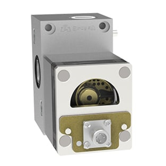
FLOW MASTER II
VOLUMETRIC FLOW METER
FOR CONTROLLING THE FLOW OF LIQUIDS
User and
Maintenance Manual
TABLE OF CONTENTS
1.
2.
3.
4.
TECHNICAL CHARACTERISTICS
5.
6.
7.
MACHINE OPERATIONS
8.
9.
10.
11.
ORDERING INFORMATION
12.
DIMENSIONS
13.
HANDLING AND TRANSPORTATION
14.
OPERATING HAZARDS
15.
PRECAUTIONS
Manual drawn up in accordance with
EC Directive 06/42
Dropsa products can be purchased from Dropsa branches and authorized distributors, visit
www.dropsa.com/contact or contact us sales@dropsa.com
C2200IE WK 27/15
Advertisement
Table of Contents

Related Manuals for DROPSA FLOW MASTER II

Summary of Contents for DROPSA FLOW MASTER II
-
Page 1: Table Of Contents
Manual drawn up in accordance with C2200IE WK 27/15 http://www.dropsa.com EC Directive 06/42 Via Benedetto Croce, 1 Vimodrone, MILANO (IT) Dropsa products can be purchased from Dropsa branches and authorized distributors, visit t. +39 02 250791 www.dropsa.com/contact or contact us sales@dropsa.com... -
Page 2: Introduction
1. INTRODUCTION This manual refers to FLOW MASTER volumetric flow device. You can find additional copies and newer revisions of this document from our website http://www.dropsa.com. Alternatively contact one of our Sales Offices. This User and Maintenance Manual contains important information on health and safety issues for the personnel. -
Page 3: Components
5. COMPONENTS METER PARTS Base Metering module Optical sensor Flow rate adjustment screw By-pass Valve 6. UNPACKING AND INSTALLATION 6.1 UNPACKING Once a suitable location has been found to install the unit remove the machine from the packaging. Check the device has not been damaged during transportation or storage. -
Page 4: Troubleshooting
Structural steel piping of proper dimensions with check valve Grip-ring pipe fittings (To assembly: block pipe fittings and tighten pipes using a vice) An inlet filter with a proper filter grade (not over 90µ), Dropsa part N°3130309 If the machine is operated for the first time: Decrease oil pumping unit pressure and ensure that all the connections are correct and there are no leaks. - Page 5 11. ORDERING INFORMATION 11.1 ASSEMBLY (base –metering module – optical sensor) STANDARD VERSION BY-PASS VERSION MATERIAL FLOW MODULE FORM Part Number Part Number ALUMINIUM 1525701 1525700 A (5 lt/min max) ALUMINIUM 1525731 1525730 B (20 lt/min max) 11.2 COMPONENTS BASE PART NUMBER THREADS MATERIAL...
- Page 6 11.4 PART NUMBER FITTING WITH NUTS AND RING FITTING WITH NUTS AND RING FITTING WITH CHECK VALVE, NUTS AND RING Ø tube Part Number Ø tube Part Number Ø tube Part Number 0,39 92374 0,31 92363 0,31 92368 0,47 92375 0,39 92270 0,39...
- Page 7 12. DIMENSIONS DEPTH “X” Module Size A (5 lt/min max) 4.33 B (20 lt/min max) 4.76 49mm 19.5mm Adjustment [1.96 in.] [0.77 in.] By-pass (optional) 24mm output GAS 3/8” [0.94 in.] UNI ISO 288/1 177.5 [6.98 in.] 43mm inlet [1.69 in.] inlet lubricant lubricant...
- Page 8 15. PRECAUTIONS No particular operating hazards characterize the FLOW MASTER, except for the following precautions: • The device is designed to operate with clean fluids not polluted by water. Presence of water can modify device reading. • Operator’s contact with lubricant during maintenance tasks: The operator must be provided with suitable personal protective clothing and devices •...
Need help?
Do you have a question about the FLOW MASTER II and is the answer not in the manual?
Questions and answers