Table of Contents
Advertisement
Quick Links
Advertisement
Table of Contents
Troubleshooting

Related Manuals for U-Line UCDE215FSS03A


Summary of Contents for U-Line UCDE215FSS03A
- Page 1 USER GUIDE & SERVICE MANUAL Model: UCDE215FSS03A...
- Page 2 USER GUIDE & SERVICE MANUAL u-line.com Table of Contents Intro Ordering Replacement Parts R600a Specifications Safety System Diagnosis Guide Safety and Warning Compressor Specifications Disposal And Recycling Troubleshooting Extended Control Operation - Service Installation Thermistor Environmental Requirements Defrost Electrical Remove Fan and Cover Cutout &...
-
Page 3: Product Information
U-Line Customer Care must be contacted immediately at +1.414.354.0300. Service or repairs performed on the unit without prior written approval from U-Line is not permitted. If the unit has been altered or repaired in the field without prior written approval from U-Line, claims will not be eligible. -
Page 4: Safety And Warning
USER GUIDE u-line.com Safety and Warning DANGER NOTICE This unit contains R600a (Isobutane) which is a Please read all instructions before installing, flammable hydrocarbon. It is safe for regular operating, or servicing the appliance. use. Do not use sharp objects to expedite defrosting. -
Page 5: Disposal And Recycling
USER GUIDE u-line.com Disposal and Recycling DANGER RISK OF CHILD ENTRAPMENT. Before you throw away your old refrigerator or freezer, take off the doors and leave shelves in place so children may not easily climb inside. If the unit is being removed from service for disposal,... -
Page 6: Environmental Requirements
USER GUIDE u-line.com Environmental Requirements This unit is designed to operate between 50°F (10°C) and 100°F (38°C). Higher ambient temperatures may reduce the unit’s ability to reach low temperatures and/or reduce ice production on applicable models. For best performance, keep the unit out of direct sunlight and away from heat generating equipment. - Page 7 USER GUIDE u-line.com Electrical WARNING SHOCK HAZARD — Electrical Grounding Required. Never attempt to repair or perform maintenance on the unit until the electricity has been disconnected. Never remove the round grounding prong from the plug and never use a two-prong grounding adapter.
-
Page 8: Cutout & Product Dimensions
12 ¼” 46 / ” (311 mm) (1,187 mm) Your U-Line product has been designed for either free- standing or built-in installation. When built-in, your unit FRONT does not require additional air space for top, sides, or rear. However, the front grille must NOT be obstructed, and clearance is required for an electrical connection in the rear. -
Page 9: Anti-Tip Bracket
USER GUIDE u-line.com Anti-Tip Bracket Slide unit out so screws on top of unit are easily accessible. Remove the two screws from the opposite side of the hinge assembly using a T-25 Torx driver (see below). Place bracket over holes and attach to unit with two screws removed in step 2 using a T-25 Torx driver. -
Page 10: General Installation
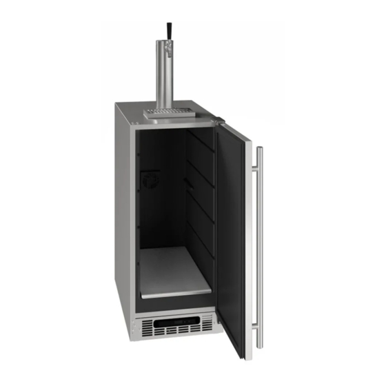
General Installation U-Line Single Tap Kits are designed to work with the U-Line keg refrigerator model CDE215F. Tap kits can be installed directly on top of the keg refrigerator in a free-standing application or through a countertop in a built-in application. The CDE215F is designed to fit one 1/6 barrel. - Page 11 USER GUIDE u-line.com Install Tower on Keg Refrigerator Do not remove the protective film on the stainless exterior until the tower is installed. Remove four screws and lift off cap plug and gasket to reveal mounting hole on top of refrigerator.
- Page 12 USER GUIDE u-line.com Install Tower on Countertop (see template at the end of this section) Use template to drill four mounting holes. Drill 2-3/4" diameter hole through countertop. Remove four Phillips screws (secured with nuts on the inside of the refrigerator) and lift off cap to reveal tower mounting hole.
- Page 13 USER GUIDE u-line.com Template for Countertop Installation Note: Verify template has printed true to scale - double check hole dimensions and placement. 1 Inch 7-1/2“ TO SIDE OF REFRIGERATOR 2-3/4“ HOLE 12-1/2“ TO FRONT FACE OF REFRIGERATOR (SEE DIAGRAM A PREVIOUS PAGE)
- Page 14 USER GUIDE u-line.com CO2 Connection NOTE: Regulator and CO2 tank not included Attach regulator to CO2 tank. Hand tighten the coupling nut and then use an adjustable wrench for an additional quarter turn. DO NOT OVER TIGHTEN Attach 5/16” CO2 tubing to regulator nipple and clamp into place. If necessary, make the tubing more pliable by heating the end in boiling water.
- Page 15 USER GUIDE u-line.com Beverage Connection NOTE: Coupler not included Attach and clamp beverage tubing to tap coupler. Attach tap coupler to keg. Locate notch and rotate clockwise turn. Press down and rotate clockwise an additional turn. Open valve on CO2 tank and adjust regulator to desired pressure by turning the handle clockwise.
-
Page 16: Leveling Information
USER GUIDE u-line.com LEVELING INFORMATION Setting CO2 Pressure Use a level to confirm the unit is level. Level should be To minimize foam for most beverages the pressure should placed along top edge and side edge as shown. be set between 8-12 PSI. -
Page 17: Grille Installation
USER GUIDE u-line.com Grille Installation REMOVING AND INSTALLING GRILLE WARNING Disconnect electric power to the unit before removing the grille. When using the unit, the grille must be installed. Removing the grille Note: Grille and display are attached. The length of the display wire is sufficient to allow access to the front base components. -
Page 18: Door Swing
USER GUIDE u-line.com Door Swing Wall 2-1/8" Min. (54 mm) 90° Door Swing Units have a zero clearance for the door to open 90°, when installed adjacent to cabinets. Stainless Steel models require 2-1/8" (54 mm) door clearance to accommodate the handle if installed next to a wall. -
Page 19: Hinge Cover
USER GUIDE u-line.com Door Adjustments TO REVERSE THE DOOR HINGE COVER Hinge cover included with the literature bag is optional. To install hinge cover: Press hinge cover squarely over hinge. Hinge Cover Remove grille: Remove the grille (see GRILLE INSTALLATION section of this guide). - Page 20 USER GUIDE u-line.com Remove door by tilting forward and lifting door off Install top hinge and door: bottom hinge. Retain shoulder washers; they will be reused. Use a Philips screwdriver to remove hinge pin and reinstall on the opposite surface of the hinge.
-
Page 21: First Use
If the temperature displayed is different than selected, the unit is progressing towards the selected temperature. Time to reach set point varies based upon ambient temperature, temperature of product loaded, door openings, etc. U-Line recommends allowing the unit to reach set points before loading. - Page 22 USER GUIDE Potential Draft Issues u-line.com WILD BEER WILD BEER CLOUDY BEER Description: Description: Beer, when drawn, is all foam, or too much When beer in glass appears hazy, not clear foam and not enough liquid beer. Causes: Causes: Frozen or nearly frozen beer...
-
Page 23: Control Operation
USER GUIDE u-line.com Control Operation CONTROL FUNCTION GUIDE FUNCTION COMMAND NOTES ON/OFF Press and hold for 5 seconds Unit will turn On or OFF When the display is flashing, press Adjust Temperature Press and release adjust the set point temperature. -
Page 24: Airflow And Product Loading
USER GUIDE u-line.com Airflow and Product Loading AIRFLOW External • Do not block the front grille - no additional clearance around sides, top or rear of unit is needed for ventilation • Do not install behind a closed door Internal •... -
Page 25: Clean Exterior Surfaces
USER GUIDE u-line.com Cleaning Note: Cleaning soaps and vinegar solutions are not CLEANING VS. SANITIZING sanitizers. This guide will address both the cleaning and the sanitizing SANITIZE INTERIOR COMPONENTS AND SURFACES of the unit. Choose a Commercial Sanitizer Safe for Stainless... -
Page 26: Continued On Next Page
USER GUIDE u-line.com Beverage Line and Faucet Cleaning Clean the system using a suitable solution designed for beer- dispensing systems. Beer cleaning kits are also available. Solution and/or kit not included. Close CO tank. Pull pin on coupler to release pressure from keg. - Page 27 USER GUIDE u-line.com Remove faucet from tower with supplied faucet wrench. Disassemble, and place all the parts in drainage bucket. 10. Add washer and attach cleaning pump connector to tower. Tighten with faucet wrench. 11. Pump all the solution through the beverage line.
- Page 28 USER GUIDE u-line.com DEFROSTING Under normal conditions this unit does not require manual defrosting. Minor frost on the rear wall or visible through the evaporator plate vents is normal and will melt during each cycle. If there is excessive build-up of 1/4” (6 mm) or more, manually defrost the unit.
-
Page 29: Cleaning Condenser
USER GUIDE u-line.com Cleaning Condenser INTERVAL - EVERY SIX MONTHS To maintain operational efficiency, keep the front grille free of dust and lint, and clean the condenser when necessary. Depending on environmental conditions, more or less frequent cleaning may be necessary. -
Page 30: Extended Non-Use
If the unit will be exposed to temperatures of 40 F (5 C) or less, the steps above must be followed. For questions regarding winterization, please call U-Line at 414.354.0300. CAUTION Damage caused by freezing temperatures is not covered by the warranty. Extended Non-Use... -
Page 31: Before Calling For Service
BEFORE CALLING FOR SERVICE • Condenser Fan: Air moving through a condenser may be heard. If you think your U-Line product is malfunctioning, read the CONTROL OPERATION section to clearly understand the • Automatic Defrost Drain Pan: Water may be heard function of the control. -
Page 32: Checking Product Temperature
USER GUIDE u-line.com u-line.com CHECKING PRODUCT TEMPERATURE Causes which affect the internal temperatures of the cabinet include: • Temperature setting. • Ambient temperature where installed. • Installation in direct sunlight or near a heat source. • The number of door openings and the time the door is open. -
Page 33: Wire Diagram
USER GUIDE u-line.com Wire Diagram Wire Diagram... -
Page 34: Product Liability
The part that caused the damage must be returned to U-Line in its entirety. The part must be clearly labeled with the serial number of the unit it was removed from, the date, and the servicer who removed the part. -
Page 35: Warranty Claims
Claims must be submitted online at • Final billing - Remodel www.U-LineService.com Warranty parts will be shipped at no charge after U-Line • 60 day submittal deadline from date of completed confirms warranty status. Please provide the model, serial service number, part number and part description. -
Page 36: Ordering Replacement Parts
Warranty parts will be shipped at no charge after U-Line confirms warranty status. Please provide the model, serial number, part number and part description. Some parts will require color or voltage information. - Page 37 Never use a torch on a fully charged refrigeration system. Never substitute U-Line OEM replacement parts or methods of construction. R-600a must be stored and transported in Technician must observe all federal, state and local laws regarding refrigerants.
- Page 38 USER GUIDE USER GUIDE u-line.com u-line.com SAFETY • INSTALLATION & INTEGRATION • OPERATING INSTRUCTIONS • MAINTENANCE • SERVICE R-600A SPECIFICATIONS/LABELING WARNING R-600a equipped products are labeled (both the unit and the compressor). Only skilled and well trained service technicians permitted to service R-600a equipped products.
-
Page 39: Leak Detection
USER GUIDE USER GUIDE u-line.com u-line.com SAFETY • INSTALLATION & INTEGRATION • OPERATING INSTRUCTIONS • MAINTENANCE • SERVICE Evacuate/reclaim via the piecing pliers to ensure the When re-brazing, the system must be purged with dry system is empty of R-600a before any system work is nitrogen and at least one access point open to the performed. - Page 40 USER GUIDE USER GUIDE u-line.com u-line.com SAFETY • INSTALLATION & INTEGRATION • OPERATING INSTRUCTIONS • MAINTENANCE • SERVICE The low side of the refrigeration system (evaporator, Proper ventilation during service is required. compressor and suction line) must be leak tested with the compressor off (equalized pressure).
-
Page 41: System Diagnosis Guide
USER GUIDE u-line.com System Diagnosis Guide REGRIGERATION SYSTEM DIAGNOSIS GUIDE System Suction Suction Compressor Condenser Capillary Evaporator Wattage Condition Pressure Line Discharge Tube Normal Normal Slightly Very hot Very hot Warm Cold Normal below room temperature Overcharge Higher than Very cold... -
Page 42: Compressor Specifications
USER GUIDE u-line.com Compressor Specifications FMXA9C REFRIGERANT R600A DANGER VOLTAGE 230 VAC FREQUENCY 43-134 Hz START WINDING 20 Ohm at 77 Electrocution can cause death or serious injury. RUN WINDING 20 Ohm at 77 Burns from hot or cold surfaces can cause serious injury. -
Page 43: Troubleshooting - Extended
• Automatic Defrost Drain Pan: Water may be heard U-Line Corp, “Customer Care Facility” at +1.800.779.2547 dripping or running into the drain pan when the unit is for assistance. in the defrost cycle. - Page 44 USER GUIDE u-line.com TROUBLESHOOTING GUIDE Concern Potential Causes Action Not Cooling Compressor overheating Verify proper air flow through condenser. Is condenser clean? Confirm condenser fan operation. Compressor not operating Test overload and relay, replace as needed. Compressor operating - no cooling Refer to System Diagnosis Guide.
-
Page 45: Main Control
USER GUIDE u-line.com MAIN CONTROL CAUTION The main control board is very robust and is rarely the cause of system issues. It is important to fully diagnose Precautions must be taken while working with the board for any suspected failures before attempting live electrical equipment. - Page 46 USER GUIDE u-line.com Control Operation-Service UI BUTTON LAYOUT Up Button -Increases temperature -Navigates through service menu -LED activated with button activation Down Button -Decreases temperature -Navigates through service menu -LED activated with button activation Light Button -Activates light for 3 hours on select models...
-
Page 47: Thermistor Failure
USER GUIDE USER GUIDE u-line.com u-line.com Thermistors Thermistor Thermistor Resistance Data Thermistor Resistance Data Nominal Resistance Thermistors are used for various temperature readings. Temp (F) Temp (C) Thermistors are used for various temperature readings. (OHMS)* Thermistors provide reliable temperature readings using a... - Page 48 USER GUIDE u-line.com Defrost Outdoor units defrost every 12 hours of compressor runtime for 45 minutes. If you have verified that the unit does not have an ambient air leak, utilize the Control Operation - Service section and adjust unit to defrost...
-
Page 49: Remove Fan And Cover
USER GUIDE u-line.com Remove Fan and Cover Remove insulating foam from refrigerant line pass- through hole as needed to gain clearance for fan plug. CONVECTION COOLING Remove internal shelving. This unit is equipped with an advanced convection cooling system. Convection cooling stabilizes cabinet temperature, Remove rear shelf clips, fronts can remain. - Page 50 USER GUIDE u-line.com 14. Remove and replace fan. Take special care to properly route fan wire. NOTICE Fan must be oriented to pull air in through lower evaporator cover vents and push air out at fan mounting location. 15. Installation is the reverse of removal.
- Page 51 For products installed and used for normal residential use, material cosmetic defects are included in this warranty, with coverage limited to 60 days from the date of original purchase. All service provided by U-Line under the above warranty must be performed by a U-Line factory authorized servicer, unless otherwise specified by U-Line.
Need help?
Do you have a question about the UCDE215FSS03A and is the answer not in the manual?
Questions and answers