
Subscribe to Our Youtube Channel
Related Manuals for Thermo 3010 Series

Summary of Contents for Thermo 3010 Series
- Page 1 Model 3010 Series Forma Water Jacketed CO Incubator Operating and Maintenance Manual Manual No: 7003010 Rev. 0...
- Page 2 Thermo Electron Corporation makes no representa- tions or warranties with respect to this manual. In no event shall Thermo be held liable for any damages, direct or incidental, aris- ing out of or related to the use of this manual.
- Page 3 Model 3010 Incubator ___________________________________________________________________________ Important operating and/or maintenance instructions. Read the accompanying text carefully. Ce symbole attire l'attention de l'utilisateur sur des instructions importantes de fonctionnement et/ou d'entretien. Il peut être utilisé seul ou avec d'autres symboles de sécurité. Lire attentivement le texte d'accompagnement. Wichtige Betriebs- und/oder Wartungshinweise.
- Page 4 Model 3010 Incubator ___________________________________________________________________________...
-
Page 5: Table Of Contents
Model 3010 Incubator ____________________________________________________________Table of Contents Table of Contents Section 1 - Installation and Start-up ....1 - 1 1.1 Name and Description of Parts ....1 - 1 1.2 Control Panel Keys, Displays and Indicators . -
Page 6: Section 1 - Installation And Start-Up
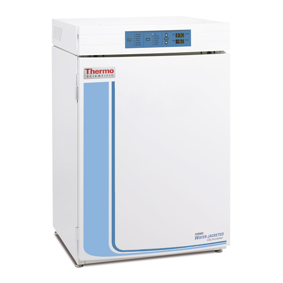
Model 3010 Incubator ________________________________________________________Installation and Start-Up Section 1 - Installation and Start-up 1.1 Name and Description of Parts Figure 1-1 Water Jacket Incubator • Outer Door - Reversible to opposite swing, see Section • Heated Inner Door - Keeps chamber interior dry. Reversible to opposite swing, see Section 4.4. -
Page 7: Control Panel Keys, Displays And Indicators
Model 3010 Incubator ________________________________________________________Installation and Start-Up Figure 1-2 Control Panel 1.2 Control Panel Keys, Displays and Indicators 1.3 Operating the Control Panel A SILENCE - Silences the audible alarm. The Model 3010 water jacket incubator has six modes, B Alarm Indicators - Specific indicator flashes during an which allow incubator setup. -
Page 8: Installing The Unit
Model 3010 Incubator ________________________________________________________Installation and Start-Up 1.4 Installing the Unit a. Choosing the Location 1. Locate the unit on a firm, level surface capable of sup- porting the unit’s operational weight of 365 lbs. (166kg). 2. Locate away from doors and windows and heating and air conditioning ducts. -
Page 9: Preliminary Cleaning And Disinfecting
Model 3010 Incubator ________________________________________________________Installation and Start-Up 6. Remove and save the two screws from the back of the control panel on the bottom unit as shown in Figure 1-8. d. Installing the Access Port Filter 7. Insert the stacking brackets into the slots on the rear of Locate the opening in the top left corner of the interior chamber. -
Page 10: Installing The Shelves
Model 3010 Incubator ________________________________________________________Installation and Start-Up g. Leveling the Unit f. Installing the Shelves Check the unit for being level by placing a bubble-style level on one of the shelves. Turn the hex nut on the leveler counterclockwise to lengthen the leg, or clockwise to shorten it. Level the unit front-to-back and left-to-right. -
Page 11: Filling The Water Jacket
Model 3010 Incubator ________________________________________________________Installation and Start-Up i. Filling the Water Jacket j. Filling the Humidity Pan Turn the power switch on. ADD WATER will appear in the For best operation of the incubator, sterilized distilled, message center. Press the Silence key to silence the alarm. demineralized or de-ionized water should be used in the humid- ity pan. - Page 12 Model 3010 Incubator ________________________________________________________Installation and Start-Up This incubator is designed to be operated with CO k. Connecting the CO Gas Supply gas only. Connecting a flammable or toxic gas can result in a hazardous condition. High concentrations of CO gas can cause asphyx- Gases other than CO should not be connected to iation! OSHA Standards specify that employee...
-
Page 13: Incubator Start-Up
Model 3010 Incubator ________________________________________________________Installation and Start-Up 1.5 Incubator Start-Up Now that the incubator has been properly installed, con- nected to power, filled with water, humidity pan filled, and con- nected to gas supply, system setpoints can be entered. The fol- lowing setpoints can be entered: temperature, over temperature, and CO To set the Overtemp setpoint:... -
Page 14: Section 2 - Calibration
Model 3010 Incubator ________________________________________________________________________Calibration Section 2 - Calibration 2.2 Calibrating Thermal Conductivity CO System This model has a thermal conductivity (T/C) CO sensor. Thermal conductivity of the incubator atmosphere is not only After the unit has stabilized, the air temperature and CO effected by the quantity of CO present, but also by the air tem- display reading can be calibrated to reference instruments. -
Page 15: Section 3 - Alarms
Model 3010 Incubator ___________________________________________________________________________Alarms Section 3 - Alarms 3.1 Alarms The Model 3010 incubator alarm system is shown in the table below. When an alarm is active, the LED next to the alarm con- dition flashes. Pressing Silence causes all active alarms to be silenced for the ringback period. However, the visual alarm continues until the incubator returns to a normal condition. - Page 16 PREVENTIVE MAINTENANCE Model 3010 Series Water Jacket Incubators Your equipment has been thoroughly tested before shipment. Regular preventive maintenance is important to keep your unit functioning properly. The operator should perform routine cleaning and maintenance on a regular basis. For maximum performance and efficiency, it is recommended the unit be checked and calibrated periodically by a qualified service technician.
- Page 17 Model 3010 Incubators ___________________________________________________________________ Preventive Maintenance Refer to Manual Action Daily Weekly Monthly 3 to 6 Yearly 2 years Section Months Check CO tank levels. Inspect door latch, hinges and door gasket seal. 1.4j Check water level in the humidity pan, ½” from top 2.1, 2.2 * Verify and document CO and temperature calibration, as...
-
Page 18: Section 4: Routine Maintenance
Model 3010 Incubator __________________________________________________________________Maintenance Section 4: Routine Maintenance 4. Remove the wingnuts securing the top duct to the interi- or. Carefully slide the top duct down and off the temper- ature sensor, air sample filter tubing. Before using any cleaning or decontamination 5. -
Page 19: Cleaning The Cabinet Exterior
Model 3010 Incubator __________________________________________________________________Maintenance 4.2 Cleaning the Cabinet Exterior 13. Install the top duct by feeding the temperature sensors, air sample tubing through the appropriate holes in the Clean the incubator exterior with a damp sponge or soft, duct as it is raised to the top of the chamber. Be careful well-wrung cloth and mild detergent dissolved in water. - Page 20 Model 3010 Incubator __________________________________________________________________Maintenance 6. Refer to item “D” in Figure 4-7A. The heater wiring 11. Remove the two nylon screws at location “G”. connector is of yellow rubber which should be visible 12. Remove the door strike plate at location “H” and install when the strain relief is moved upward as shown.
- Page 21 Model 3010 Incubator __________________________________________________________________Maintenance 23. When both hinges are in place with the hinge screws 21. Push the power cable completely into the slot in the still loosened, push up on the bottom hinge. This will electronics tray. Press the tray into position and secure shift both hinges and the door upward.
- Page 22 Model 3010 Incubator __________________________________________________________________Maintenance 25. Attach the outer door hinges at the “P” locations. 26. Install the nylon screws at the “R” locations. 27. Install the nylon screws in the “Q” locations. 28. Assemble the outer door to the incubator and return the unit to service.
-
Page 23: Replacing Fuses
Model 3010 Incubator __________________________________________________________________Maintenance Figure 4-8, Electronics Drawer There are two fuses on the main microboard labeled ‘F1 24VAC Door Heater’ and ‘F4 24VAC Collar Heater’. Refer to 4.5 Replacing Fuses Figure 4-8 for the location of the main microboard. Remove the fuse and replace it with a new one of the same specification. -
Page 24: Replacing The Air Sample Filter
Model 3010 Incubator __________________________________________________________________Maintenance 4.6 Replacing the Air Sample Filter The air sample filter should be replaced as needed; every 6 months is recommended. On the inside of the chamber, insert- ed into the back of the blower scroll, is the air sample filter and its connecting tubing. -
Page 25: Section 5 - Remote Alarm
Model 3010 Incubator _______________________________________________________________________Remote Alarm Section 5 - Remote Alarm 5.1 Connecting the Remote Alarm Contacts A set of relay contacts are provided to monitor alarms through an RJ-11 telephone style connector on the back of the cabinet. Refer to Figure 1-13 for the location of the alarm con- nector. -
Page 26: Section 6 - Specifications
Model 3010 Incubator ______________________________________________________________________Specifications Section 6 - Specifications *Specifications are based on nominal voltages of 115V in ambients of 22°C to 25°C. Temperature Control ±0.1°C Range +5°C above ambient to +55°C (131°F) Uniformity ±0.3°C @ +37°C Low Temp Tracking Alarm Fixed at 1.0°C below setpoint Temperature Safety Sensor... - Page 27 Model 3010 Incubator ______________________________________________________________________Specifications Construction Water Jacket Volume 11.7 gal. (43.5 liters) Interior Volume 6.5 cu. ft. (184.1 liters) Interior Type 304 2B finish, stainless steel Exterior 18 gauge, cold rolled steel, powder coated Outer Door Gasket Four-sided, molded magnetic vinyl Inner Door Gasket Removable, cleanable, feather-edged, silicone Electrical...
-
Page 28: Section 7 - Spare Parts
Model 3010 Incubator ________________________________________________________________Spare Parts Section 7 - Spare Parts Part # Description 360171 Liquid Level Switch 191534 Feather Gasket 113002 5/16-18 Glide Foot 132046 115/230V Dual Heater 132056 Face Heater 27W, 24VAC 1900203 Heated Inner Door 700046 Lower Inner Door Hinge Nylon Bearing 700013 Upper Inner Door Hinge Nylon Bearing 990026... - Page 30 Model 3010 Incubator ________________________________________________________________Spare Parts 7 - 3...
- Page 31 Model 3010 Incubator ________________________________________________________________Spare Parts 7 - 4...
- Page 33 Model 3010 Incubator __________________________________________________________Electrical Schematics 8 - 1...
- Page 34 Model 3010 Incubator __________________________________________________________Electrical Schematics 8 - 2...
- Page 35 The Technical Services Department must give prior approval for return of any components or equipment. At Thermo's option, all non-conforming parts must be returned to Thermo Electron Corporation postage paid and replacement parts are shipped FOB destination.
- Page 36 The Technical Services Department must give prior approval for return of any components or equipment. At Thermo's option, all non-conforming parts must be returned to Thermo postage paid and replacement parts are shipped FOB destination.
- Page 37 Thermo Electron Corporation Controlled Environment Equipment Millcreek Road, P.O. Box 649 Marietta, Ohio 45750 U.S.A. Telephone (740) 373-4763 Telefax (740) 373-4189...
Need help?
Do you have a question about the 3010 Series and is the answer not in the manual?
Questions and answers