Table of Contents
Advertisement
Quick Links
Advertisement
Table of Contents

Subscribe to Our Youtube Channel
Related Manuals for GigaDevice Semiconductor GD32E507R-START


Summary of Contents for GigaDevice Semiconductor GD32E507R-START
- Page 1 GigaDevice Semiconductor Inc. GD32E507R-START User Guide V1.0...
-
Page 2: Table Of Contents
User Guide GD32E507R-START Tables of Contents TABLES OF CONTENTS ....................1 LIST OF FIGURES ......................3 LIST OF TABLES ......................4 1. SUMMARY ........................ 5 2. FUNCTION PIN ASSIGN ................... 5 3. GETTING STARTED ....................5 4. HARDWARE LAYOUT OVERVIEW ................6 4.1. - Page 3 User Guide GD32E507R-START 5.7.1. DEMO Purpose ........................14 5.7.2. DEMO Running Result ......................15 6. REVISION HISTORY ....................16 2/17...
-
Page 4: List Of Figures
User Guide GD32E507R-START List of Figures Figure 4-1. Schematic diagram of power supply ..................6 Figure 4-2. Schematic diagram of boot option ..................6 Figure 4-3. Schematic diagram of LED function ..................6 Figure 4-4. Schematic diagram of Key function ..................7 Figure 4-5. -
Page 5: List Of Tables
User Guide GD32E507R-START List of Tables Table 2-1. Function pin assignment ......................5 Table 6-1. Revision history ........................16 4/17... -
Page 6: Summary
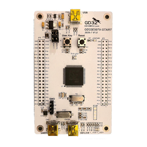
GD32E507R-START Summary GD32E507R-START uses GD32E507RET6 as the main controller. It uses GD-Link Mini USB interface to supply 5V power. Reset, Boot, K2-User Key, LED, USB and USART to USB interface are also included. For more details please refer to GD32E507R-START-Rev1.1 schematic. -
Page 7: Hardware Layout Overview
User Guide GD32E507R-START Hardware layout overview 4.1. Power supply Figure 4-1. Schematic diagram of power supply +3V3 +U5V +5V0 AMS1117-3.3 LEDPWR 16V/10uF,AVX 16V/10uF,AVX Vout 470Ω LED0603 SMD1210P005TF 50V/0.1uF 50V/0.1uF 4.2. Boot option Figure 4-2. Schematic diagram of boot option 4.3. -
Page 8: Key
User Guide GD32E507R-START 4.4. Figure 4-4. Schematic diagram of Key function 4.5. USART Figure 4-5. Schematic diagram of USART 4.6. Figure 4-6. Schematic diagram of USB 7/17... -
Page 9: Extension
User Guide GD32E507R-START +5V0 47KΩ S8550 470R 16V/10uF,AVX 50V/0.1uF USB_VBUS VBUS PA11 USB_DM PA12 USB_DP Shield Mini_USB 1MΩ 50V/4700pF 4.7. Extension Figure 4-7. Schematic diagram of Extension Extension Pin HEADER 6 4.8. GD-Link Figure 4-8. Schematic diagram of GD-Link 8/17... -
Page 10: Arduino
User Guide GD32E507R-START +3V3 JP100 PA0-WKUP L_SWDIO PB2/BOOT1 L_SWDCK PB3/JTDO L_TMS/IO PB4/JNTRST L_TCK/CLK 4× 1P2.54 L_TDO/SWO L_TDI L_USB_Ctr L_TReset Reset PA10 PB10 L_USB_DM PA11 PB11 L_USB_DP LED0603 PA12 PB12 +3V3 L_SWDIO L_LED2 R110 L_LED2 470Ω PA13/JTMS/SWDIO PB13 C100 49SMD-8MHz L_SWDCK... -
Page 11: Mcu
User Guide GD32E507R-START 4.10. Figure 4-10. Schematic diagram of MCU GDLink JTAG +3V3 PA0-WKUP L_TDI JTDI PA15 L_TMS/IO JTMS/SWDIO PA13 PB2/BOOT1 L_TCK/CLK JTCK/SWDCLK PA14 PB3/JTDO L_TDO/SWO JTDO PB4/JNTRST L_TReset NRST 4× 1P2.54 PA10 PB10 PA10 PB10 49SMD-25MHz PA11 PB11 PA11... -
Page 12: Routine Use Guide
Learn to use SysTick to generate 1ms delay GD32E507R-START-V1.1 board has 2 keys and four LEDs. The keys are User Key and Reset Key. The LEDs are controlled by GPIO. This demo will show how to light the LEDs. -
Page 13: Exti_Key_Interrupt_Mode
Learn to use EXTI to generate external interrupt GD32E507R-START-V1.1 board has 2 keys and four LEDs. The keys are User Key and Reset Key. The LEDs are controlled by GPIO. This demo will show how to use the EXTI interrupt line to control the LED2. When press down the User Key, it will produce an interrupt. -
Page 14: Timer_Key_Exti
Learn to use TIMER to generate PWM GD32E507R-START board has two keys and four LEDs. The two keys are Reset key and User key. The LED1, LED2, LED3 and LED4 are controlled by GPIO. This demo will show how to use the TIMER PWM to trigger EXTI interrupt to toggle the state of LED2 and EXTI interrupt line to control the LED1. -
Page 15: Demo Running Result
Learn the operation between the HID host and the keyboard device GD32E507R-START board integrates the USBHS module, and the module can be used as a USB device, a USB host or an OTG device. This demo mainly shows how to use the USBHS as a USB HID host to communicate with external USB HID device. - Page 16 User Guide GD32E507R-START 5.7.2. DEMO Running Result Download the program < 07_USB_HID_Host > to the start board and run. If a mouse has been attached, the user will see the information of mouse enumeration. First pressing the USER key will see the inserted device is mouse, and then moving the mouse will show the position of mouse in the HyperTerminal.
- Page 17 User Guide GD32E507R-START Revision history Table 6-1. Revision history Revision No. Description Date Initial Release Aug.14, 2020 16/17...
- Page 18 Important Notice This document is the property of GigaDevice Semiconductor Inc. and its subsidiaries (the "Company"). This document, including any product of the Company described in this document (the “Product”), is owned by the Company under the intellectual property laws and treaties of the People’s Republic of China and other jurisdictions worldwide.
Need help?
Do you have a question about the GD32E507R-START and is the answer not in the manual?
Questions and answers