Table of Contents
Advertisement
Quick Links
Advertisement
Table of Contents

Related Manuals for Astralpool 71245


Summary of Contents for Astralpool 71245
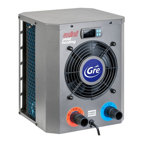
- Page 1 MINI HEATER User and Service manual - 1 -...
- Page 2 - 2 -...
- Page 3 Mini Heater User and Service manual INDEX 1. Specifications 2. Dimension 3. Installation and connection 4. Electrical Wiring 5. Display Controller Operation 6. Exploded Diagram 7. Maintenance Thank you for using Mini Heater for your pool heating, it will heat your pool water and keep the constant temperature when the air ambient temperature is above 12 ℃...
-
Page 4: Specifications
1. Specifications 1.1 Technical data pool heat pumps Item 71245 71258 71606 Air 28℃, Water 28℃, Humidity 80% Heat Output (kW) Power Consumption (kW) 0.59 1.31 Air 15℃, Water 26℃, Humidity 70% Heat Output (kW) Power Consumption (kW) 0.56 0.91... - Page 5 2. Dimension (mm) Item 71245 356.5 71258/71606 131.5 50.7 432.5 - 5 -...
-
Page 6: Installation And Connection
3. Installation and connection 3.1 Notes The factory supplies only the heat pump. All other components, must be provided by the user or the installer. Install a bypass if the water flow from the swimming pool pump is more than 20% greater than the allowable flow through the heat exchanger of the heat pump. - Page 7 3.4 Check-valve installation Note: If automatic dosing equipment for chlorine and acidity (pH) is used, it is essential to protect the heat pump against excessively high chemical concentrations which may corrode the heat exchanger. For this reason, equipment of this sort must always be fitted in the piping on the downstream side of the heat pump, and it is recommended to install a check-valve to prevent reverse flow in the absence of water circulation.
-
Page 8: Electrical Wiring
4. Electrical Wiring 4.1 SWIMMING POOL HEAT PUMP WIRING DIADRAM 71245 - 8 -... - Page 9 71258/71606 NOTE: (1)Above electrical wiring diagram only for your reference, please subject machine posted the wiring diagram. (2)The swimming pool heat pump must be connected ground wire well, although the unit heat exchanger is electrically isolated from the rest of the unit .Grounding the unit is still required to protect you against short circuits inside the unit .Bonding is also required.
-
Page 10: Display Controller Operation
5. Display Controller Operation The buttons of LED wire controller 5.2 When the heat pump is running, the LED display shows the water inlet temperature. LED 1 is on when compressor is running. LED 2 is on if trouble. 5.3 Turn on/off the heat pump Press to turn on the heat pump, the LED display shows the water setting temperature for 5s, then show water inlet temperature. -
Page 11: Exploded Diagram
6.Exploded Diagram 71245 No. Spare parts No. Spare parts 1 Top cover 15 Front panel 2 Pillar 16 Base 3 Ambient temp. sensor 17 Titanium exchanger 4 Transition tube 18 Coupling tube 5 Gas collecting pipe 19 Water in temp. sensor... - Page 12 71258/71606 No. Spare parts No. Spare parts 1 Pillar 15 Power cord buckle 2 Top cover 16 Base 3 Evaporator 17 Titanium exchanger 4 Ambient temp. sensor 18 Water in temp. sensor 5 Electric box 19 Global valve 6 Fan capacitor 20 Gas collecting pipe 7 Capillary 21 Globe valve panel...
-
Page 13: Maintenance
7. Maintenance (1) You should check the water supply system regularly to avoid the air entering the system and occurrence of low water flow, because it would reduce the performance and reliability of HP unit. (2) Clean your pools and filtration system regularly to avoid the damage of the unit as a result of the dirty of clogged filter. - Page 15 A0158MHS03...
Need help?
Do you have a question about the 71245 and is the answer not in the manual?
Questions and answers