Table of Contents
Advertisement
Quick Links
Advertisement
Table of Contents

Related Manuals for LDA Audio Tech VCC 64

Summary of Contents for LDA Audio Tech VCC 64
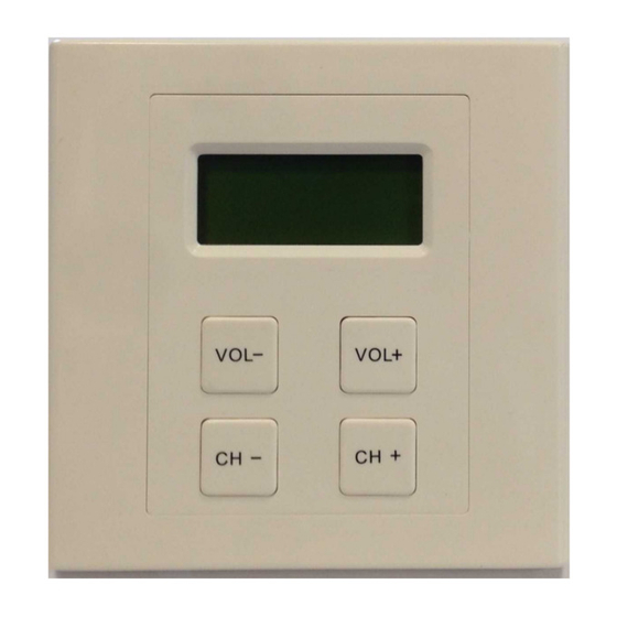
- Page 1 User's Manual VCC 64 – Volume and Channel Controller Model: VCC-64...
-
Page 3: Table Of Contents
Index 1 INTRODUCTION........................... 1 2 DESCRIPTION..........................1 2.1 INPUTS AND OUTPUTS......................1 2.1.1 DATA BUS / POWER SUPPLY...................... 2 2.1.2 BUS ADDRESS..........................2 3 CONNECTION..........................3 4 FUNCTIONING..........................4 4.1 QUIESCENCE MODE........................4 4.2 ACTIVE MODE..........................4 4.3 AUTOMATIC LOCK........................5 5 FAULT RESOLUTIONS........................ 6 5.1 SCREEN IS BLANK........................6 5.2 THE NUMBER OF SOURCES AND VOLUME SOES NOT APPEAR ON SCREEN.... - Page 4 LDA Audio Tech - Severo Ochoa 31- 29590 MÁLAGA, SPAIN. Tlf: +34 952028805...
- Page 5 SECURITY INSTRUCTIONS 1. Please read carefully these safety instructions. 2. Keep this User Manual for future reference. 3. Unplug the equipment from the AC before cleaning. 4. Do not use liquid or sprayed detergent for cleaning. 5. Use a cloth for cleaning. 6.
-
Page 7: Introduction
User's manual: VCC-64 1 INTRODUCTION The VCC-64 allows up to 64 programmable channels and volume control (0-9). Usually installed in local zone and connected via bus to the system, it offers source selection, volume control and lock function. FEATURES: 1. Source selection (1-64) 2. -
Page 8: Data Bus / Power Supply
The VCC-6 has a DIP-Switch to configure the address in the bus RS-485. Every controller assigned to the same zone, should have the same address configuration. For different zones different address should be assigned. LDA Audio Tech - Severo Ochoa 31- 29590 MÁLAGA, SPAIN. Tlf: +34 952028805... -
Page 9: Connection
User's manual: VCC-64 Ilustration 2: Address Switch 3 CONNECTION The VCC-64 is connected to the system's interface through bus mode, and every VCC-64 will be connected from each other. Only one of the VCC-64 has to be connected to the system's interface. This way the unit located closer to the system will be connected to the interface, and from this unit to the next VCC-64. -
Page 10: Functioning
Once unlocked, press VOL+ to raise the volume level of the zone and VOL- to lower it. The following table of equivalence shows the relationship between the volume indicated in the VCC-64 and the gain associated to the zone. LDA Audio Tech - Severo Ochoa 31- 29590 MÁLAGA, SPAIN. Tlf: +34 952028805... -
Page 11: Table 2: Volume - Zone Gain
User's manual: VCC-64 VOLUME GAIN -3dB -6dB -10dB -15dB -21dB -28dB -36dB -45dB -100dB Table 2: Volume - Zone Gain To change the audio source assigned to the zone, press the buttons CH+ and CH-. The display will show the change in the number of the source. The number displayed corresponds to the number of the source in the PA system. -
Page 12: Automatic Lock
Do not use aerosol sprays, solvents or abrasives. • Do not spray any cleaning products directly on the device. Operations: • Wipe the system with a damp cloth. LDA Audio Tech - Severo Ochoa 31- 29590 MÁLAGA, SPAIN. Tlf: +34 952028805... -
Page 13: Technical Specifications
User's manual: VCC-64 7 TECHNICAL SPECIFICATIONS Model VCC-64 Reference LDAVCC64S02 Power supply 12V DC consumption 1,2 max (100mA) Bus RS-485 Maximum distance 1000m/ 3280,8 ft. MAX 8 VCC-64 by bus Address Dip-swithc 3 bit Volume Buttons VOL- / VOL+ Volume Steps Source Buttons CH+ / CH- Channel Range... - Page 14 Rev 3,1...
Need help?
Do you have a question about the VCC 64 and is the answer not in the manual?
Questions and answers