Table of Contents

Related Manuals for HELLA Aglaia Advanced People Sensor


Summary of Contents for HELLA Aglaia Advanced People Sensor
- Page 1 Version 1.18.0 Advanced People Sensor APS-90, APS-180 and APS-90-Outdoor-PoE Installation and configuration manual Installation and configuration manual (original) HAGL-120-00077 HELLA Aglaia People Sensing Technologies people-sensing.com...
- Page 2 +49 30 2000429-109 email: support@people-sensing.com www.people-sensing.com © 2020 HELLA Aglaia Mobile Vision GmbH, Berlin Version 1.18.0 The reproduction, distribution and utilization of this document as well as the communication of its contents to others without 2 / 179 express authorization is prohibited. Offenders will be held liable for the payment of damages.
- Page 3 HELLA Aglaia Mobile Vision GmbH reserves the right to revise or replace this manual at any time and without prior notice. Make sure that you have the appropriate version of this manual for the installed firmware version of the device. If you have any questions, please contact HELLA Aglaia Mobile Vision GmbH.
-
Page 4: Table Of Contents
Scope of delivery ..........12 Use of the Advanced People Sensor ....... . 13 Privacy of data statement . - Page 5 APS-90, APS-180 and APS-90-Outdoor-PoE Table of contents 3.2.10 Digital I/O ........... . . 36 3.2.11 Remote access .
- Page 6 APS-90, APS-180 and APS-90-Outdoor-PoE Table of contents Installation ........65 Requirements .
- Page 7 APS-90, APS-180 and APS-90-Outdoor-PoE Table of contents 6.4.3 Floor Area ........... . 98 6.4.4 Obstructions .
- Page 8 APS-90, APS-180 and APS-90-Outdoor-PoE Table of contents 6.10.3 Ethernet DNS ..........122 6.10.4 Proxy .
- Page 9 APS-90, APS-180 and APS-90-Outdoor-PoE Table of contents 6.14.5 Open Source Licenses ......... 142 6.14.6 Contact Addresses .
-
Page 10: Overview
APS-90, APS-180 and APS-90-Outdoor-PoE Overview Overview The Advanced People Sensor (APS) counts persons within the configured area/monitored area based on stereoscopic imaging and image processing. The counting data is stored internally and can be transferred via different interfaces for external processing. -
Page 11: General Information
APS-90, APS-180 and APS-90-Outdoor-PoE General information General information About this document This manual provides information for optimal configuration and efficient operation of the device. Personnel must carefully read and fully understand this manual before performing any installation or configuration tasks. The figures in this manual are for information only. -
Page 12: About The Manufacturer
The obligations agreed upon in the delivery contract, General terms and conditions and delivery conditions of HELLA Aglaia as well as any legal regulations applicable at the time of the contract conclusion apply. -
Page 13: Use Of The Advanced People Sensor
General information Use of the Advanced People Sensor Intended use The Advanced People Sensor is a sensor assembly, which must be integrated into other systems. The Advanced People Sensor is intended for automatically counting persons in the config- ured monitored area. - Page 14 APS-90, APS-180 and APS-90-Outdoor-PoE General information Changing linux passwords APS9029B6 login: root Password: counter ~ # passwd customer Changing password for customer New password: new123password Retype password: new123password passwd: password for customer changed by root ~ # passwd hagl Changing password for hagl New password: new987password Retype password: new987password passwd: password for hagl changed by root...
-
Page 15: Structure And Function
APS-90, APS-180 and APS-90-Outdoor-PoE Structure and function Structure and function Hardware 3.1.1 APS-90 Housing Fig. 2: Housing view: connection side APS-90E-IO (interfaces) USB 2.0 interface Factory reset button Ethernet interface RJ45 Status LED Power and I/O interface (only APS-90E-IO) Version 1.18.0 The reproduction, distribution and utilization of this document as well as the communication of its contents to others without 15 / 179 express authorization is prohibited. - Page 16 APS-90, APS-180 and APS-90-Outdoor-PoE Structure and function Fig. 3: Housing view: optics side Ethernet port on device Pin no. Name Description TxRx A + Transmit/Receive A (positive polarity) TxRx A − Transmit/Receive A (negative polarity) TxRx B + Transmit/Receive B (positive polarity) Fig.
- Page 17 APS-90, APS-180 and APS-90-Outdoor-PoE Structure and function I/O port on device Pin no. Name Description PWRIN+ DC voltage supply + (alternative to PoE, 18 ... 29 V) IN1+ Programmable input + IN2+ Programmable input + Fig. 5: I/O interface ("A": optics orientation) IN3+ Programmable input + OUT1+...
- Page 18 APS-90, APS-180 and APS-90-Outdoor-PoE Structure and function 3.1.2 APS-180 Housing Fig. 7: Housing view: connection side APS-180E-IO (interfaces) USB 2.0 interface Factory reset button Ethernet interface RJ45 Status LED Power and I/O interface (only APS-180E-IO) Fig. 8: Housing view: optics side USB port on device Pin no.
- Page 19 APS-90, APS-180 and APS-90-Outdoor-PoE Structure and function Ethernet port on device Pin no. Name Description TxRx A + Transmit/Receive A (positive polarity) TxRx A − Transmit/Receive A (negative polarity) TxRx B + Transmit/Receive B (positive polarity) Fig. 10: RJ45 ethernet interface TxRx C + Transmit/Receive C (positive polarity)
-
Page 20: Aps-90-Outdoor-Poe
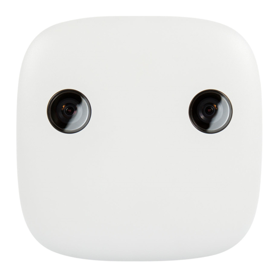
APS-90, APS-180 and APS-90-Outdoor-PoE Structure and function 3.1.3 APS-90-Outdoor-PoE Housing Fig. 12: Housing I/O interface (D-SUB), X2 Fixing points (2 x 2 M5) Right HDR camera Status LED Left HDR camera Ethernet interface (M12), X1 Ground stud (metric thread M5), PE Ethernet port on device Pin no. - Page 21 APS-90, APS-180 and APS-90-Outdoor-PoE Structure and function I/O port on device Pin no. Name Description Reset Reset Pin (leave open, only required for corrective mainte- nance) Fig. 14: I/O interface OUT1 + Programmable output +, potential-free ("A": optics orientation) IN1 + Programmable input +, potential-free IN2 + Programmable input +, potential-free...
-
Page 22: Status Led
APS-90, APS-180 and APS-90-Outdoor-PoE Structure and function 3.1.4 Status LED Starting the device takes about 40 seconds. During this time the status LED is as follows: When the device starts the LED is illuminated in red for approximately 10 sec. ■... -
Page 23: Factory Reset Button/Pin
APS-90, APS-180 and APS-90-Outdoor-PoE Structure and function 3.1.5 Factory reset button/pin The device must be powered for using the button/pin. On an APS-90 or APS-180 press the button gently with a pencil. On an APS-90-Outdoor-PoE connect the reset pin 1 of the I/O port with pin 12. The device will change the LED illumination as feedback. -
Page 24: Functionality
APS-90, APS-180 and APS-90-Outdoor-PoE Structure and function Functionality Fig. 16: People sensing Advanced People Sensor (APS) Configured area/monitored area Counting line The device continually acquires stereoscopic video images in its visual range. The integrated software evaluates the stereoscopic images. Persons within the monitored area are recognized automatically and their movements are tracked across the subse- quent images. -
Page 25: Counting
APS-90, APS-180 and APS-90-Outdoor-PoE Structure and function 3.2.1 Counting 3.2.1.1 Counting lines A counting line is represented by a colored polyline with lettered points at floor level. Fig. 17: Counting lines Counting is bidirectional and achieved by drawing polylines with triangular markers pointing inwards, indicating counting direction. - Page 26 APS-90, APS-180 and APS-90-Outdoor-PoE Structure and function Fig. 18: Example Floor area Counting line There are three modes for counting persons who turn around in the monitored floor area: No delay ■ Counts every time a person crosses the counting line, without suppressing U-turns (immediate result after crossing the counting line).
-
Page 27: Counting Groups
APS-90, APS-180 and APS-90-Outdoor-PoE Structure and function 3.2.1.3 Counting groups Optional function This function can only be enabled if a corresponding license file is installed on the device. This functionality is included in the Object Classification license ( Software Options on page 156). With this functionality the device counts groups (shop- ping units). -
Page 28: Object Classification
APS-90, APS-180 and APS-90-Outdoor-PoE Structure and function It is used to detect the number of people in that zone, e.g. how many people are currently in a lock gate, elevator or in front of a cash point. Based on this information maximum and average dwell times are calculated and displayed in the user interface. -
Page 29: Object List
APS-90, APS-180 and APS-90-Outdoor-PoE Structure and function Fig. 20: Example of classification with adults (red), child (yellow) and cart (blue) 3.2.4 Object list Optional function This function can only be enabled if a corresponding license file is installed on the device. This function creates a list of current objects (persons). -
Page 30: Multi Sensor Fusion
APS-90, APS-180 and APS-90-Outdoor-PoE Structure and function Height: 128 Age: 45 Height: 178 Height: 182 Age: 135 Age: 45 Fig. 21: Example of object list 3.2.5 Multi Sensor Fusion With the Multi Sensor Fusion it is possible to combine up to 10 sensors. With this fusion a wide entrance could be covered with multiple sensors and used by fusion to a master sensor with only one wide counting line. - Page 31 APS-90, APS-180 and APS-90-Outdoor-PoE Structure and function The maximum monitored area can be extended from 8 m x 8 m (26.2 ft x 26. ft) with 1 device up to 8 m x 22.8 m (26.2 ft x 74.7 ft) with 2 devices and so on. Fig.
-
Page 32: Optical Self Diagnosis
APS-90, APS-180 and APS-90-Outdoor-PoE Structure and function 3.2.6 Optical Self Diagnosis The device checks its visible range permanently. The status of this optical self diagnosis (OSD) is shown in the user interface. Normal state. Covered One or both cameras covered, e.g. by a sticker. Too dark Illumination is too low for proper function or both cameras are completely covered and show a black image. -
Page 33: Video Recording
APS-90, APS-180 and APS-90-Outdoor-PoE Structure and function 3.2.7 Video recording Optional function This function can only be enabled if a corresponding license file is installed on the device. Customers are recommended to record videos including data (e.g. count data) to validate the accuracy of the sensor. - Page 34 APS-90, APS-180 and APS-90-Outdoor-PoE Structure and function The "APS Video Player" (Windows version only) can be used to view these recordings. It can export plain video files with selected overlays (to be played with standard video tools) for the end customer. Use the latest "APS Video Player"...
-
Page 35: Video Streaming
APS-90, APS-180 and APS-90-Outdoor-PoE Structure and function 3.2.8 Video streaming Optional function This function can only be enabled if a corresponding license file is installed on the device. Video streaming allows live camera images to be streamed over the network and viewed live on a client using software like VLC media player or recorded in a video recorder. -
Page 36: Wireless Services
The device can be used in combination with a wireless USB adapter. There are two options for now. One for WiFi only and one for WiFi and Bluetooth. These are preselected by HELLA Aglaia to use the correct driver software inside the firmware. Using these wireless USB adapters, 3 modes for WiFi are available:... -
Page 37: Remote Access
Application areas Indoor The Advanced People Sensor APS-90 and APS-180 can be used in buildings for counting people in front of doors and passageways or in corridors and stairwells. Typical applica- tion areas are retail shops, showrooms, train stations and airports. -
Page 38: Interfaces
APS-90, APS-180 and APS-90-Outdoor-PoE Structure and function Outdoor For outdoor application such as theme parks, please use the APS-90-Outdoor-PoE or APS-180E with additional outdoor housing. Data is transferred via Ethernet. Interfaces Interface / User Digital Data Video REST REST Push MQTT Google available data... - Page 39 The password by default is admin Operation As soon as the installation, initial operation and configuration are completed, the Advanced People Sensor starts counting and tracking automatically without a PC. The counting data is transferred via the corresponding configured interfaces. Version 1.18.0...
-
Page 40: Digital Inputs / Outputs
APS-90, APS-180 and APS-90-Outdoor-PoE Structure and function 3.4.2 Digital inputs / outputs Digital Input Digital inputs are available on the following devices: Device Digital inputs APS-90E-IO APS-180E-IO APS-90-Outdoor-PoE APS-90-IO-8GB APS-180-IO-8GB The digital input can be used instead of a counting line. In this use case an external device sends an impulse as counting information. - Page 41 APS-90, APS-180 and APS-90-Outdoor-PoE Structure and function The files can be automatically uploaded by the file upload service to a ftp or sftp server. The device takes care of correctly uploading to the server. In situations of a network shortage or reboot (e.g.
- Page 42 APS-90, APS-180 and APS-90-Outdoor-PoE Structure and function Counting data Example Data file recording settings: Counting line "countA" Completion interval 3 hours Sample rate 15 min License without Object Classification license record_id timestamp period status countA_SUM_IN countA_SUM_OUT 13089 2020-04-01 18:15:00 "0" 13090 2020-04-01 18:30:00 "0"...
- Page 43 APS-90, APS-180 and APS-90-Outdoor-PoE Structure and function record_id: Unique ID for the data line (after ID 4294967295 it restarts with 0) timestamp: Timestamp of device is adjusted to local time when writing the data line period: Sample rate in seconds for the summation status: OSD status - see values below 0 OK...
- Page 44 APS-90, APS-180 and APS-90-Outdoor-PoE Structure and function Countevent data Example Data file recording settings: Completion interval 15 min record_id timestamp period status line event_typ class 2020-04-01 14:30:15 "0" Polyline0 1740 Adult 2020-04-01 14:30:18 "0" Polyline0 Group 2020-04-01 14:35:19 "0" Polyline0 1850 Adult 2020-04-01 14:35:11...
- Page 45 APS-90, APS-180 and APS-90-Outdoor-PoE Structure and function Wireless tracking data Example Data file recording settings: Completion interval 15 min Sample rate 30 sec scan_id timestamp period mac_addr wireless_type_IN signal_stre ngth 5971 2020-04-01 14:30:15 84:8E:DF:01:23:45 WIFI 5971 2020-04-01 14:30:15 94:65:9C:98:76:54 WIFI 5971 2020-04-01 14:30:15 E0:C7:67:AB:CD:EF...
- Page 46 APS-90, APS-180 and APS-90-Outdoor-PoE Structure and function Zone statistics data Example Data file recording settings: Zone statistics completion interval 5 min Monitored zones EntranceZone ExitZone Data recording completion interval 15 min record_id timestamp period status zone SUM_ SUM_m SUM_m SUM_m count ax_fill_ axDwell...
- Page 47 APS-90, APS-180 and APS-90-Outdoor-PoE Structure and function If the optional function "Object Classification" is available (by installing the license) the summations are separated into known classes and columns, so instead of the simple col- umns above (SUM_count, SUM_max_fill_level, SUM_maxDwell and SUM_meanDwell) they will be categorized instead as below: Adult_count: Number of adults...
- Page 48 APS-90, APS-180 and APS-90-Outdoor-PoE Structure and function Zone objectlist data Example 2020-04-11 "0" "inFloor" 4313 "Adu 2020-04-11 10:35:00 lt" 10:32:46 2020-04-11 "0" "inFloor" 5067 "Adu 2020-04-11 10:32:46 lt" 10:33:52 2020-04-11 "0" "inFloor" 5237 "Adu 2020-04-11 10:33:52 lt" 10:34:05 2020-04-11 "0" "InR206Fr 5278 "Adu...
- Page 49 APS-90, APS-180 and APS-90-Outdoor-PoE Structure and function dwell_time: (M) Length of stay in the zone during the interval height: (N) Height of the object Zoneevent data Example Data file recording settings: Completion interval 15 min record_id timestamp period status zone event_typ class 2020-04-01 14:30:15...
-
Page 50: Rest Api (Poll)
XML. The integrated REST API answers to requests from a server. Fig. 28: APS server communication via REST No Part The server is not part of the HELLA Aglaia offer. Detailed Information For detailed protocol information see the APS-RS-Manual-REST-API. -
Page 51: Rest Push
REST with JSON containers called "REST Push". Fig. 29: APS server communication via REST Push No Part The server is not part of the HELLA Aglaia offer. Detailed Information For detailed protocol information see the APS-RS-Manual-REST-Push. Version 1.18.0... -
Page 52: Push Service Via Soap/Xml
As a response to device messages the server can pass new tasks to the device e.g. to send counting messages every ten minutes. No Part The server is not part of the HELLA Aglaia offer. Detailed Information For detailed protocol information see the APS-RS-Manual-Push- Service-via-SOAP. -
Page 53: Google Pub/Sub
APS-90, APS-180 and APS-90-Outdoor-PoE Structure and function 3.4.8 Google Pub/Sub A simple interface to push the data to the Google Cloud. Fig. 30: Push Service to Google Cloud Platform Detailed Information For detailed protocol information see the APS-RS-Manual-Google- Pub_Sub. 3.4.9 PS Platform A simple interface to push the data to the PS Platform (PS.P). -
Page 54: Technical Data
APS-90, APS-180 and APS-90-Outdoor-PoE Technical data Technical data Mechanical data 4.1.1 APS-90 Category Description Dimensions 159.5 mm x 159.5 mm x 41.4 mm (6.3 in x 6.3 in x 1.7 in) Weight 430 g (14 oz) Material Plastic & Aluminum (ADC12) Fig. - Page 55 APS-90, APS-180 and APS-90-Outdoor-PoE Technical data 4.1.2 APS-180 Category Description Dimensions 237.5 mm x 99.2 mm x 36.7 mm (9.3 in x 3.9 in x 1.5 in) Weight 600 g (21 oz) Material Aluminum (ADC12) Fig. 33: APS-180 dimensions Version 1.18.0 The reproduction, distribution and utilization of this document as well as the communication of its contents to others without 55 / 179 express authorization is prohibited.
-
Page 56: Aps-90-Outdoor-Poe
APS-90, APS-180 and APS-90-Outdoor-PoE Technical data 4.1.3 APS-90-Outdoor-PoE Category Description Dimensions 140.8 mm x 98.2 mm x 35.0 mm (5.54 in x 3.87 in x 1.38 in) Weight 440 g (15.17 oz) Material Aluminum (ADC12) Fig. 34: APS-90-Outdoor-PoE dimensions Hardware interface specifications 4.2.1 Ethernet 4.2.1.1... -
Page 57: Aps-90-Outdoor-Poe
APS-90, APS-180 and APS-90-Outdoor-PoE Technical data Pin allocation on device Pin no. Name Ethernet mode A mode B TxRx A + Transmit/Receive A (positive DC + polarity) TxRx A − Transmit/Receive A (negative DC + Fig. 35: RJ-45 Ethernet polarity) interface (arrow "A": optics orientation) TxRx B +... -
Page 58: I/O Port
APS-90, APS-180 and APS-90-Outdoor-PoE Technical data Pin allocation on device Pin no. Name Description Transmit data + Receive data + Transmit data - Receive data - Shield Fig. 36: M12 Ethernet interface ("A": optics orientation) Compatibility of APS-90-Out- APS-90-Outdoor-PoE door-PoE and PoE switches Port M12 D-coded (4 RJ45 pins) -
Page 59: Aps-180E-Io And Aps-180-Io
APS-90, APS-180 and APS-90-Outdoor-PoE Technical data Pin no. Name Description OUT3+ Programmable output + PWRIN- DC voltage supply - (alternative to PoE, 18 ... 29 V) IN1- Programmable input - IN2- Programmable input - IN3- Programmable input - OUT1- Programmable output - OUT2- Programmable output - OUT3-... - Page 60 APS-90, APS-180 and APS-90-Outdoor-PoE Technical data Pin no. Name Description IN2- Programmable input - IN2+ Programmable input + IN1- Programmable input - IN1+ Programmable input + PWRIN- DC voltage supply - (alternative to PoE, 18 ... 29 V) PWRIN+ DC voltage supply + (alternative to PoE, 18 ...
-
Page 61: Aps-90-Outdoor-Poe
APS-90, APS-180 and APS-90-Outdoor-PoE Technical data 4.2.2.3 APS-90-Outdoor-PoE Pin allocation on device Pin no. Name Description Reset Reset Pin (leave open, only required for corrective mainte- nance) OUT1 + Programmable output +, potential-free Fig. 40: D-SUB I/O Interface IN1 + Programmable input +, potential-free ("A": optics orientation) IN2 +... -
Page 62: Electrical Data
APS-90, APS-180 and APS-90-Outdoor-PoE Technical data Electrical data Supply voltage Category Description Input voltage U (PD class 0) via Ethernet 36 .. 57 V DC Power consumption P (without USB load) 6 W (125 mA at 48 V DC) Ethernet APS-90 APS-90-Outdoor- APS-180... -
Page 63: Environmental Conditions
APS-90, APS-180 and APS-90-Outdoor-PoE Technical data Environmental conditions Category APS-180E APS-90 APS-90-Out- door-PoE APS-180 Operating temperature -25 to 70 °C 0 to 55 °C (32 -25 to 70 °C (-13 to 158 °F) to 131 °F) (-13 to 158 °F) (ambient temperature housing) Storage temperature -40 to 85 °C (-40 to 185 °F) -
Page 64: Product Labels
APS-90, APS-180 and APS-90-Outdoor-PoE Technical data Product labels Identification Label Fig. 42: Identification label The identification plate contains the following information: Manufacturer name Production country Production date Serial number / MAC address Certification markings (e.g. CE) Preinstalled licenses Software / Firmware version Hardware model Part number Product name (e.g. -
Page 65: Installation
APS-90, APS-180 and APS-90-Outdoor-PoE Installation Installation Requirements Mounting position Consider the following requirements when selecting the mounting position: Fig. 44: Mounting position Ensure that the mounting position and the holder / protective housing provide suffi- ■ cient stability. Ensure that the mounting position is in the right place: ■... - Page 66 APS-90, APS-180 and APS-90-Outdoor-PoE Installation If the view in the visual range is impaired, the obstructed area can be defined. Ensure that the area is sufficiently illuminated. ■ Mounting parameters APS-90 APS-180 APS-90-Outdoor- Mounting height 2.0 .. 6.0 m 3.0 .. 9.0 m 2.0 ..
-
Page 67: Mounting The Aps-90
APS-90, APS-180 and APS-90-Outdoor-PoE Installation Table 1: Monitored area (detailed information Chapter 9.1 Detection area on page 151 ) Installation height Width (X) Depth (Z) [ft] [ft] [ft] 2.00 6.56 1.85 6.07 1.60 5.25 3.00 9.84 3.90 12.80 3.30 10.83 4.00 13.12... -
Page 68: Recessed Mounting
APS-90, APS-180 and APS-90-Outdoor-PoE Installation Click the APS-90 with faceplate into place in the surface mount box. Observe sequence To unmount it, first remove the faceplate and then open the three clips of the surface mount box. 5.2.2 Recessed mounting Drill a hole of 144 - 150 mm (5.6 - 5.9 in). - Page 69 APS-90, APS-180 and APS-90-Outdoor-PoE Installation Mount the three screws and flaps, and rotate the flaps so they are tucked in close to the counter body. Fix it with the three screws and flaps - or the 4 screw holes depending to the ceiling material.
- Page 70 APS-90, APS-180 and APS-90-Outdoor-PoE Installation Attach the ethernet cable. Mount the faceplate. Version 1.18.0 The reproduction, distribution and utilization of this document as well as the communication of its contents to others without 70 / 179 express authorization is prohibited. Offenders will be held liable for the payment of damages. 21.04.2020 All rights reserved in the event of the grant of patent, utility model or design.
-
Page 71: Mounting The Aps-180
APS-90, APS-180 and APS-90-Outdoor-PoE Installation Mounting the APS-180 5.3.1 Surface mounting Fig. 48: Fixing points Fix the APS-180 to the ceiling. Attach the ethernet cable to the APS-180. To mount the cover of the APS-180 put the hood on and slide it in. Version 1.18.0 The reproduction, distribution and utilization of this document as well as the communication of its contents to others without 71 / 179... -
Page 72: Recessed Mounting
APS-90, APS-180 and APS-90-Outdoor-PoE Installation 5.3.2 Recessed mounting Mount the bracket inside the ceiling. Click the APS-180 into place and attach the ethernet cable. Version 1.18.0 The reproduction, distribution and utilization of this document as well as the communication of its contents to others without 72 / 179 express authorization is prohibited. - Page 73 APS-90, APS-180 and APS-90-Outdoor-PoE Installation To install the cover of the APS-180 put the hood on and slide it in by hand. Version 1.18.0 The reproduction, distribution and utilization of this document as well as the communication of its contents to others without 73 / 179 express authorization is prohibited.
-
Page 74: Wiring Examples
APS-90, APS-180 and APS-90-Outdoor-PoE Installation Wiring examples 5.4.1 APS-90E-IO and APS-90-IO Digital input with an IR- The following example shows a wiring diagram with an infrared sensor sensor as digital input. Observe the following electrical limit values: = 100 mA = 30 VDC Fig. - Page 75 APS-90, APS-180 and APS-90-Outdoor-PoE Installation Digital output with potential- The following examples shows wiring diagrams for the potential-free free contacts digital output contacts. Observe the following electrical limit values: = 100 mA = 30 VDC Fig. 50: APS-90 Digital output with potential-free contacts Fig.
-
Page 76: Aps-180E-Io And Aps-180-Io
APS-90, APS-180 and APS-90-Outdoor-PoE Installation 5.4.2 APS-180E-IO and APS-180-IO Digital input with an IR- The following example shows a wiring diagram with an infrared sensor sensor as digital input. Observe the following electrical limit values: = 100 mA = 30 VDC Fig. - Page 77 APS-90, APS-180 and APS-90-Outdoor-PoE Installation Digital output with potential- The following examples shows wiring diagrams for the potential-free free contacts digital output contacts. Observe the following electrical limit values: = 100 mA = 30 VDC Fig. 54: APS-180 Digital output with potential-free contacts Fig.
-
Page 78: Aps-90-Outdoor-Poe
APS-90, APS-180 and APS-90-Outdoor-PoE Installation 5.4.3 APS-90-Outdoor-PoE Digital input with an IR- The following example shows a wiring diagram with an infrared sensor sensor as digital input. Observe the following electrical limit values: = 100 mA = 30 VDC Fig. 57: Digital input with an IR-sensor Version 1.18.0 The reproduction, distribution and utilization of this document as well as the communication of its contents to others without 78 / 179... - Page 79 APS-90, APS-180 and APS-90-Outdoor-PoE Installation Digital output with potential- The following examples shows wiring diagrams for the potential-free free contacts digital output contacts. Observe the following electrical limit values: = 100 mA = 30 VDC Fig. 58: APS-Outdoor Digital output with potential-free contacts Fig.
-
Page 80: Multi Sensor Fusion
APS-90, APS-180 and APS-90-Outdoor-PoE Installation Multi Sensor Fusion Up to 10 sensors can be merged to monitor large areas. Fig. 61: Fusion of 4 sensors In this sensor array it is possible to define up to 10 counting lines and up to 8 monitored zones. - Page 81 APS-90, APS-180 and APS-90-Outdoor-PoE Installation Requirements For the selection of the installation site it is important that the monitored areas of the ■ individual devices overlap by at least 100 cm or 3.3 ft (Fig. 63 /1). DNS Service Discovery is available in the network. ■...
- Page 82 APS-90, APS-180 and APS-90-Outdoor-PoE Installation Basic configuration slaves Configuring the slaves Configure a slave device as slaves. Scan for Master device. List of all master devices is shown. Select the master device. The status of the connection changes to working. Repeat for all other slaves Automatic configuration The automatic configuration determines the positions and arrangement of the devices in...
- Page 83 APS-90, APS-180 and APS-90-Outdoor-PoE Installation Fig. 65: Around a corner Fig. 66: Multiple overlaps parallel lines Fig. 67: Multiple overlaps staggered lines Version 1.18.0 The reproduction, distribution and utilization of this document as well as the communication of its contents to others without 83 / 179 express authorization is prohibited.
-
Page 84: Configuration
Access your router or DHCP Software to find the IP address used by the device. Search for the unique MAC address of the device. The MAC address starts with 00:0b:91 for HELLA Aglaia devices. Fig. 68: Fetching the used IP address (example) Version 1.18.0... -
Page 85: Determine The Ip Address Without The Dhcp Server
APS-90, APS-180 and APS-90-Outdoor-PoE Configuration 6.1.2 Determine the IP address without the DHCP server If there is no access to the DHCP server, you can find out the IP address via Bonjour SDK. This tool is often available through printer drivers on the PC. It can also be installed via http://www.dns-sd.org/ClientSetup.html. -
Page 86: Connect The Aps
APS-90, APS-180 and APS-90-Outdoor-PoE Configuration 6.1.3 Connect the APS Start a web browser and enter the IP address (e.g. 192.168.100.32). The welcome screen of the device appears. Fig. 69: Welcome screen and login Enter login password depending on whether Login Read- Only Login for Setup access is needed. -
Page 87: Basic Operations
APS-90, APS-180 and APS-90-Outdoor-PoE Configuration Basic Operations The device has a web based user interface for configuration. During configuration, a browser window refresh can cause the loss of unsaved settings from the current view. The design of the user interface is responsive. The appearance of the user interface depends on the used configuration device. -
Page 88: Camera View
APS-90, APS-180 and APS-90-Outdoor-PoE Configuration 6.2.1 Camera view Some of the menu categories use a camera view to configure areas or lines. This view can be a live view or a still image. Fig. 71: Camera view Camera View Show/Hide button for overlay infor- mation Play button to show live view Forward button to refresh still... -
Page 89: Status Bar
APS-90, APS-180 and APS-90-Outdoor-PoE Configuration 6.2.2 Status bar The user interface has a status bar below. Fig. 72: Status bar Hostname of the device Date and time on the device Web interface to sensor connection Firmware version status indicated by a heart Connection OK: heart flashing green-grey Connection stopped: heart in red 6.2.3... -
Page 90: Navigation Bar
APS-90, APS-180 and APS-90-Outdoor-PoE Configuration 6.2.4 Navigation bar The user interface has a navigation bar on the left. Use the arrow icon to expand or col- lapse the navigation bar. Some of the icons only appear if a corresponding license file is installed. Select an icon to go to a certain configuration category. -
Page 91: Changing Values, Areas And Lines
APS-90, APS-180 and APS-90-Outdoor-PoE Configuration 6.2.5 Changing Values, Areas and Lines Fig. 74: Configuration options Changing Values To go to the next input field (Fig. 74 /3) or button click in an input field or use the <tab> key. Edit the entry or choose from a list of values. ... -
Page 92: Start Page - Live View
APS-90, APS-180 and APS-90-Outdoor-PoE Configuration Start Page - live view To go to the Start Page - Live View page click the home icon (Fig. 75 /1). This page appears after Login and shows a camera view, the status of the device and counting infor- mation. -
Page 93: Device Information
APS-90, APS-180 and APS-90-Outdoor-PoE Configuration For a live view click the button (Fig. 76 /4). The button changes to a button ■ during live view. To refresh view if live view is paused click the button (Fig. 76 /5). The button is ■... -
Page 94: Counts
APS-90, APS-180 and APS-90-Outdoor-PoE Configuration 6.3.3 Counts Counting Information for up to 10 counting lines can be shown. Fig. 78: Counts with 1 counting line To show or hide the counting line in the live view use the button (Fig. 78 /1). ■... -
Page 95: Monitored Zones
APS-90, APS-180 and APS-90-Outdoor-PoE Configuration 6.3.4 Monitored Zones Counts how many persons are inside a zone for up to 8 monitored zones can be shown. Fig. 79: Counts with 1 monitored zone To show or hide the monitored zones in the live view use the button (Fig. -
Page 96: Camera Position Setup
APS-90, APS-180 and APS-90-Outdoor-PoE Configuration Camera Position Setup To go to the Camera Position Setup page click the Camera Position icon (Fig. 80 /1). Fig. 80: Camera Position Setup In order to obtain correct counting results, the position and alignment of the device at the installation site must be set. -
Page 97: Height Range
APS-90, APS-180 and APS-90-Outdoor-PoE Configuration If measurement is not possible - e.g. a consistently level floor area is not big enough - the device presents a ‘not available’ hint (Fig. 81 /1). In this case use a separate measuring device and set up the values manually. The height is the distance between the device level and the floor level. -
Page 98: Floor Area
APS-90, APS-180 and APS-90-Outdoor-PoE Configuration Fig. 82: Height Range To set the device for low height select (Fig. 82 /5). ■ To set the device for standard height select Standard (Fig. 82 /4). ■ To set the device for extended height select Extended (Fig. -
Page 99: Obstructions
APS-90, APS-180 and APS-90-Outdoor-PoE Configuration To define the floor area (Fig. 83 /3) in the live view activate the Edit button (Fig. 84 /3). ■ To see the unusable area (Fig. 83 /1) and usable area (Fig. 83 /2) click the Range ■... -
Page 100: Coordinate System
APS-90, APS-180 and APS-90-Outdoor-PoE Configuration 6.4.5 Coordinate System The feature "Object List" reports the position of people and objects. By default the coordinate system axis is right below the sensor, with the positive x-axis to the right and positive y-axis to the top of the camera view respectively. Fig. -
Page 101: Multi Sensor Fusion
APS-90, APS-180 and APS-90-Outdoor-PoE Configuration Multi Sensor Fusion To go to the Multi Sensor Fusion Setup page click the Multi Sensor Fusion icon (Fig. 90 /1). Fig. 90: Multi Sensor Fusion Setup Define the device as a part of a multi sensor fusion. Fig. -
Page 102: Configure The Master Device
APS-90, APS-180 and APS-90-Outdoor-PoE Configuration 6.5.1 Configure the master device When configuring the device as a master determine the slave devices. Fig. 92: Slave devices To manually add a slave device click the plus button (Fig. 92 /1). ■ To find slave devices automatically scan for slave devices by clicking the Scan for ■... -
Page 103: Configure The Slave Devices
APS-90, APS-180 and APS-90-Outdoor-PoE Configuration Fig. 94: Connected slave device When the connection between a slave and master is established the status (Fig. 94 /5) ■ changes to unconfigured. The hostname (Fig. 94 /4) and the IP address (Fig. 94 /3) of a connected slave are ■... -
Page 104: Complete The Setup
APS-90, APS-180 and APS-90-Outdoor-PoE Configuration Fig. 96: Select master device To select the master device mark a device (Fig. 96 /1) and click the Select button ■ (Fig. 96 /3). To leave the window without selecting a device click the Abort button (Fig. -
Page 105: Counting
APS-90, APS-180 and APS-90-Outdoor-PoE Configuration Counting To go to the People Counting Setup page click the Counting icon (Fig. 98 /1). Fig. 98: People Counting Setup The device can use up to 10 individual bi-directional counting lines. A counting line is represented by a colored polyline with lettered points at floor level. The line has a triangular marker which indicates the direction of incoming persons, and this can be switched. - Page 106 APS-90, APS-180 and APS-90-Outdoor-PoE Configuration If the counting line is not edited see the configuration (Fig. 100 /10). ■ To show or hide the counting line in the live view click the button (Fig. 100 /9). ■ To edit the line in the live view click the button (Fig.
-
Page 107: Count Events
APS-90, APS-180 and APS-90-Outdoor-PoE Configuration 6.6.2 Count events The device can log every single count events for the counting lines. Fig. 101: Count events To activate logging count events tick the Count events checkbox (Fig. 101 /3). ■ To go back to the last saved settings click the Reset button (Fig. -
Page 108: Zone Monitoring
APS-90, APS-180 and APS-90-Outdoor-PoE Configuration Zone Monitoring Optional function This function can only be enabled if a corresponding license file is installed on the device. To go to the Zone Monitoring Setup page click the Zone Monitoring icon (Fig. 103 /1). Fig. -
Page 109: Additional Zone Data
APS-90, APS-180 and APS-90-Outdoor-PoE Configuration Each configured monitored zone is listed with its configuration and monitoring data ■ information. The monitored zone is specified with an identifier (Fig. 105 /4 or /19) and a name ■ (Fig. 105 /5). It is possible to see the counting information of the monitored zone for Adults and ■... -
Page 110: Monitoring Filter
APS-90, APS-180 and APS-90-Outdoor-PoE Configuration To activate the logging of events entering or leaving a zone, tick the Zone Events ■ checkbox (Fig. 106 /7). To activate the generation of the statistical values, tick the Zone Statistics checkbox ■ (Fig. 106 /6). To change the interval during which the statistics are collected, select a Completion ■... -
Page 111: Video
APS-90, APS-180 and APS-90-Outdoor-PoE Configuration Video Optional function This function can only be enabled if a corresponding license file is installed on the device. To go to the Video Service Settings page click the Video icon (Fig. 108 /1). Fig. 108: Video Service Settings 6.8.1 Video recording The Devices can store video files locally. -
Page 112: Video Streaming
APS-90, APS-180 and APS-90-Outdoor-PoE Configuration To activate Video recording select Video Recording (Fig. 109 /13) on. ■ See the state of recording (Fig. 109 /12). ■ Choose a Resolution (Fig. 109 /11) from the drop down list. ■ Choose a Frame rate (Fig. -
Page 113: Video File Access
APS-90, APS-180 and APS-90-Outdoor-PoE Configuration To activate Video Streaming select the mode Video Streaming (Fig. 110 /9). Choose a Video mode (Fig. 110 /1) from the drop down list. 2D (color video) and 3D ■ (disparity image) is possible. Choose a Resolution (Fig. -
Page 114: Data Interface
APS-90, APS-180 and APS-90-Outdoor-PoE Configuration To limit the storage time tick Limit Storage Period checkbox (Fig. 111 /18). ■ For automatic deletion set up a Storage Period (Fig. 111 /17). The period must be ■ between 1 and 8760 hours. For automatic upload of completed files tick File Upload checkbox (Fig. -
Page 115: Push Service
APS-90, APS-180 and APS-90-Outdoor-PoE Configuration 6.9.1 Push service If a Push Service is used, the device sends (pushes) data to a server to which the device has established a connection. Upon initial contact the server informs the device of the required data and transmission times. -
Page 116: Rest Push
APS-90, APS-180 and APS-90-Outdoor-PoE Configuration To add the sensor to an IBM Watson IoT Platform account enter the Watson Organiza- ■ tion ID (Fig. 114 /1). To add the sensor to a group of sensors at the IBM Watson IoT Platform account enter ■... -
Page 117: Google Pub/Sub
APS-90, APS-180 and APS-90-Outdoor-PoE Configuration 6.9.1.4 Google Pub/Sub To enable push service to the Google platform activate Google Pub/Sub (Fig. 116 /8). Fig. 116: Push Service - Google Pub/Sub To add the sensor to an Google Platform account enter the Project ID (Fig. -
Page 118: Rest Api
APS-90, APS-180 and APS-90-Outdoor-PoE Configuration 6.9.2 REST API Fig. 118: REST API Use REST API is activated (Fig. 118 /1), a server can pull the device to send data. Set the REST API Server Port (Fig. 118 /2). ■ To go back to the last saved settings click the Reset button (Fig. -
Page 119: Data File Access
APS-90, APS-180 and APS-90-Outdoor-PoE Configuration To activate the recording of counting data tick the Record Counting Data checkbox ■ (Fig. 119 /9). To define the period within which counts are accumulated and new data lines are ■ attached to the current data file set a Accumulation Interval (Fig. -
Page 120: Network
APS-90, APS-180 and APS-90-Outdoor-PoE Configuration For automatic upload select a Protocol Type (Fig. 120 /13) and set the Server Address ■ and the Server port (Fig. 120 /12). To access the upload server set the Server User Name (Fig. 120 /11), the Server User ■... -
Page 121: Ethernet Ip
APS-90, APS-180 and APS-90-Outdoor-PoE Configuration 6.10.2 Ethernet IP Fig. 122: IP The device is usable with dynamic IP by DHCP or static IP. Hostname (Fig. 122 /1) identifies the device in the network, data recording files ■ and protocols. Select the input field and type a name that represents the installation location. -
Page 122: Ethernet Dns
APS-90, APS-180 and APS-90-Outdoor-PoE Configuration 6.10.3 Ethernet DNS Fig. 123: DNS Domain Name System servers translate FQDN like "www.people-sensing.com" to an IP address. Typically it is received from the DHCP server. If you use fixed IP addresses and also use FQDN (instead of IP addresses) you need to set the DNS. Select the input field and type an IP address for the preferred (Fig. -
Page 123: Network Services
APS-90, APS-180 and APS-90-Outdoor-PoE Configuration 6.10.5 Network Services Fig. 125: Network Services For reasons of IT security, it is recommended to disable all network services that are not needed. To activate/deactivate Telnet to the device (in most cases only required for mainte- ■... -
Page 124: Hmi
APS-90, APS-180 and APS-90-Outdoor-PoE Configuration 6.10.6 Fig. 126: User interface access Set the HMI Protocol Type as a standard HTTP connection or as a secured HTTPS con- ■ nection (Fig. 126 /1). Set the HMI Server Port (Fig. 126 /2). ■... -
Page 125: Vpn Auto Connection
APS-90, APS-180 and APS-90-Outdoor-PoE Configuration 6.10.7 VPN Auto Connection Fig. 127: VPN Auto Connection To connect to the device via a VPN connection, activate Enable VPN (Fig. 127 /1) ■ Use Control Server is activated (Fig. 127 /2) the device checks periodically the ■... -
Page 126: Wireless Services
APS-90, APS-180 and APS-90-Outdoor-PoE Configuration 6.11 Wireless Services Optional function This function can only be enabled if a corresponding license file is installed on the device. To go to the Wireless Services Settings page click the Wireless Services icon (Fig. 128 /1). Fig. -
Page 127: Wifi Mode
APS-90, APS-180 and APS-90-Outdoor-PoE Configuration If the wireless USB adapter is attached to the sensor at startup and is working, the ■ <up> WiFi Device State (Fig. 129 /8) shows If the Bluetooth USB adapter is attached, the Bluetooth Device State (Fig. -
Page 128: Wifi Mode Tracking
APS-90, APS-180 and APS-90-Outdoor-PoE Configuration 6.11.3 WiFi Mode Tracking The device can track wireless devices such as smartphones. The device can save this tracking data to CSV files. Fig. 131: Wireless tracking To track wireless devices such as mobile phones choose the WiFi Mode WirFi Tracking ■... -
Page 129: Wifi Hmi Access
APS-90, APS-180 and APS-90-Outdoor-PoE Configuration 6.11.4 WiFi HMI Access Set up the details for use as an access point: Fig. 132: WiFi HMI Access To access the HMI with wireless devices choose the WiFi Mode WirFi HMI Access ■ (Fig. 132 /15). To choose legal frequency spectrum select your region code ("US"... -
Page 130: Wifi Data Interface
APS-90, APS-180 and APS-90-Outdoor-PoE Configuration To connect to the device in Access Point mode, choose the device SSID in the WiFi list e.g. <People_Sensor> of your notebook and connect with your password (default is ). To open the user interface use the AP IP address (Fig. 132 /10). 6.11.5 WiFi Data Interface To send counting and other data wirelessly the device must login to a wireless network. -
Page 131: Bluetooth Mode
APS-90, APS-180 and APS-90-Outdoor-PoE Configuration 6.11.6 Bluetooth Mode The APS can use the Bluetooth USB adapter to track Bluetooth devices. Fig. 134: Bluetooth Mode To track Bluetooth devices such as mobile phones choose the Bluetooth Mode Blue- ■ tooth Tracking (Fig. -
Page 132: Other Settings
APS-90, APS-180 and APS-90-Outdoor-PoE Configuration 6.12 Other Settings To go to the Other Settings page click the Other Settings icon (Fig. 135 /1). Fig. 135: Other Settings Use the Other Settings page to set date and time manually, to locate the sensor, to set the usage of the LED or to change the login passwords. -
Page 133: Find Me
APS-90, APS-180 and APS-90-Outdoor-PoE Configuration Set the time zone by choosing region and location (Fig. 136 /1) from the dropdown ■ boxes. NTP (Fig. 136 /2) should be activated to set the correct time and date automatically ■ after reboot. Using NTP the IP address of the timeserver (Fig. 136 /3) has to be defined. -
Page 134: Led Configuration
APS-90, APS-180 and APS-90-Outdoor-PoE Configuration 6.12.3 LED Configuration The status LED is switched off after start-up. With the LED Configuration the status LED can be activate for some events. Fig. 138: LED Configuration To display the operation of the device activate Working (Fig. -
Page 135: Service Tools
APS-90, APS-180 and APS-90-Outdoor-PoE Configuration 6.13 Service Tools To go to the Service Tools page click the Service Tools icon (Fig. 140 /1). Fig. 140: Service Tools This page provides miscellaneous tools that are usually only needed by the service techni- cian. -
Page 136: Firmware Update
Configuration 6.13.2 Firmware Update Fig. 142: Firmware Update The firmware can be updated with a firmware file provided by Hella Aglaia. To start the ■ update click Start Update Process (Fig. 142 /1) and select the firmware file (*.tar) on the PC. -
Page 137: Parameter Import
6.13.5 Diagnosis Data Fig. 145: Diagnosis Data For HELLA Aglaia customer support, it can be useful to provide diagnostic data that ■ can be exported from the device. To download the file click Get Diagnosis Data (Fig. 145 /1). -
Page 138: License File Import
APS-90, APS-180 and APS-90-Outdoor-PoE Configuration 6.13.6 License File Import Fig. 146: License File Import Some additional features of the device require installed licenses. In order to enable ■ these features, you need to copy the corresponding license files to the device. To upload the file click Import a License File (Fig. -
Page 139: Factory Reset
APS-90, APS-180 and APS-90-Outdoor-PoE Configuration 6.13.8 Factory reset Fig. 148: Factory Reset Under certain circumstances it might be necessary to reset all the parameter settings ■ of the device to their factory default settings. To reset the parameters to the default settings of the installed firmware version click ■... -
Page 140: Device Information
APS-90, APS-180 and APS-90-Outdoor-PoE Configuration 6.14.1 Device information Fig. 150: Device Information Device Information shows the Serial Number (same as MAC hardware address), Hard- ware Type (circuit board), Model and Firmware Version. 6.14.2 Installed licenses Fig. 151: Installed Licenses Some additional features of the device require installed licenses. Installed License shows all licenses with their status of validity. - Page 141 APS-90, APS-180 and APS-90-Outdoor-PoE Configuration The Hostname identifies the device by a given name and is also used in protocols and ■ saved files. The Default Gateway is the numerical path used to connect the device to other parts of ■...
-
Page 142: System Health Status
APS-90, APS-180 and APS-90-Outdoor-PoE Configuration 6.14.4 System health status Fig. 153: System Health Status This information shows: Operating time since last start. ■ Overall operating time. ■ Operating time since last firmware update. ■ Type of last system reset or reboot/restart. ■... -
Page 143: Contact Addresses
APS-90, APS-180 and APS-90-Outdoor-PoE Configuration 6.14.6 Contact Addresses Fig. 155: Contact Addresses The manufacturer and customer support can be contacted via these addresses. 6.15 Diagnostics To go to the Diagnostics and Test Images page click the Diagnostics icon (Fig. 156 /1). Fig. -
Page 144: Counts
APS-90, APS-180 and APS-90-Outdoor-PoE Configuration 6.15.1 Counts Shows the counting data depending on the configuration and the installed license. Fig. 157: Counts with 1 counting line The counting line is specified with its identifier (Fig. 157 /8) and its name (Fig. 157 /7). ■... -
Page 145: Monitored Zones
APS-90, APS-180 and APS-90-Outdoor-PoE Configuration 6.15.2 Monitored Zones Fig. 158: Monitored zones Click the button (Fig. 158 /1) to show or hide the monitored zone in the live view. ■ See the actual number of objects in the monitored zones (Fig. 158 /2). The data is split ■... -
Page 146: Usb Video Recording
USB Video Recording USB Video Recording function is for connecting USB memory devices but is aimed at HELLA Aglaia development issues (not for customer use). This video recording does not include any counting or tracking data. <Data Recording> The customer video recording is located at the menu icon Fig. -
Page 147: Cleaning, Maintenance And Troubleshooting
APS-90, APS-180 and APS-90-Outdoor-PoE Cleaning, maintenance and troubleshooting Cleaning, maintenance and trouble- shooting Cleaning Materials: Lint-free cloth Commonly available neutral cleaners diluted with water Optimal counting accuracy can be achieved only if the view of the cameras is not obstructed. Check the lens cover plate or outside housing for dirt, scratches and stickers at reg- ular intervals. - Page 148 APS-90, APS-180 and APS-90-Outdoor-PoE Cleaning, maintenance and troubleshooting Fault description Cause Remedy Status LED blinks permanently Device is in DHCP mode and receives Check the DHCP server in the network. yellow no IP address. Device has no connection to the Power supply interrupted Check power supply.
- Page 149 APS-90, APS-180 and APS-90-Outdoor-PoE Cleaning, maintenance and troubleshooting Fault description Cause Remedy If checks are negative, reconfigure the device. Modified mounting position Check in the user interface: If the adjusted pitch and yaw angle still ■ correspond to the values measured on the device.
-
Page 150: Disposal
In the European Union, the WEEE Directive 2012/19/EU applies. HELLA Aglaia will recollect its own electronic products free of charge and take care of the further processing. Decommissioned devices can be sent to the address: HELLA Aglaia Mobile Vision GmbH Ullsteinstraße 140 12109 Berlin Germany Please clearly mark the goods as waste. -
Page 151: Appendix
APS-90, APS-180 and APS-90-Outdoor-PoE Appendix Appendix Detection area Fig. 162: Detection area lengths in cm Version 1.18.0 The reproduction, distribution and utilization of this document as well as the communication of its contents to others without 151 / 179 express authorization is prohibited. Offenders will be held liable for the payment of damages. 21.04.2020 All rights reserved in the event of the grant of patent, utility model or design. - Page 152 APS-90, APS-180 and APS-90-Outdoor-PoE Appendix Fig. 163: Detection area lengths in inch Version 1.18.0 The reproduction, distribution and utilization of this document as well as the communication of its contents to others without 152 / 179 express authorization is prohibited. Offenders will be held liable for the payment of damages. 21.04.2020 All rights reserved in the event of the grant of patent, utility model or design.
- Page 153 APS-90, APS-180 and APS-90-Outdoor-PoE Appendix Fig. 164: Detection area lengths in feet Version 1.18.0 The reproduction, distribution and utilization of this document as well as the communication of its contents to others without 153 / 179 express authorization is prohibited. Offenders will be held liable for the payment of damages. 21.04.2020 All rights reserved in the event of the grant of patent, utility model or design.
-
Page 154: Ordering Information
APS-90, APS-180 and APS-90-Outdoor-PoE Appendix Ordering Information The device and the accessories listed can be ordered from HELLA Aglaia using the fol- lowing order numbers. Contact Please contact HELLA Aglaia for other versions and accessory parts. info@people-sensing.com www.people-sensing.com Product Product Description Order no. - Page 155 APS-90, APS-180 and APS-90-Outdoor-PoE Appendix Product Description Order no. APS-90-Outdoor-PoE Advanced People Sensor 013.929-037 outdoor sensor (IP65) for ceiling heights from 2.0 m - 4.00 m (78.74 in - 157.48 in) with digital inputs Discontinued products Old order no. Product Description Order no.
- Page 156 APS-90, APS-180 and APS-90-Outdoor-PoE Appendix Software Options Option Description Order no. Object Classification Separate count values e.g. for adults, 921.700-13B children, groups and shopping carts. Zone Monitoring Amount of people in visible areas. 921.700-14B Object List Actual and/or historical list of detected 921.700-11B objects with location, height and other parameters sent via Push Services...
-
Page 157: Menu Structure
APS-90, APS-180 and APS-90-Outdoor-PoE Appendix Accessories Accessory Description Order no. Wireless USB adapter Wireless tracking of devices or 226.167-007 WiFi connection USB WiFi Bluetooth Adapter Wireless tracking of devices or WiFi 226.167-017 connection and Bluetotth tracking APS-90 faceplate white Installation kit 226.140-007 APS-90 faceplate black Installation kit... - Page 158 APS-90, APS-180 and APS-90-Outdoor-PoE Appendix Menu View Comment Home Device Information Status of the visible range and the configuration of the programmable inputs Counts Counting Information for up to 10 counting lines Monitored Zones Live amount results Camera view Live view with counting lines and tracking objects Camera Position Camera Position Adjust the mounting angles...
- Page 159 APS-90, APS-180 and APS-90-Outdoor-PoE Appendix Menu View Comment Data File Recording File completion interval for counting data, zone monitoring data and wireless tracking data Data File Access Settings and usage of automatic file upload and manual access to stored files Network Ethernet Network Status Current network status...
-
Page 160: List Of Used Ip Ports
System Health Status Uptime, CPU temperature, cause of last reboot, etc. Open Source Licenses Information about used components in the firm- ware Contact Addresses HELLA Aglaia contact data Diagnostics Counts Live counting results Monitored Zones Live amount results Tracked Object List Visualization... - Page 161 APS-90, APS-180 and APS-90-Outdoor-PoE Appendix Direction Port TCP/UDP Description HTTPS Internal web server ➨APS (user interface) configurable UDP/TCP Resolving IP for FQDN APS➨ (Domain Name System) APS➨ Clock synchronization (Network Time Protocol) Push Services Push data to server via http APS➨...
- Page 162 APS-90, APS-180 and APS-90-Outdoor-PoE Appendix Direction Port TCP/UDP Description RTSP External control of Video Streaming ➨APS (Real Time Streaming Protocol) configurable Watson IoT Authentifizierung für MQTT APS➨ Watson IoT APS➨ 8883 MQTT Datenübertragung Version 1.18.0 The reproduction, distribution and utilization of this document as well as the communication of its contents to others without 162 / 179 express authorization is prohibited.
-
Page 163: Ce Declaration Of Conformity
APS-90, APS-180 and APS-90-Outdoor-PoE Appendix CE Declaration of Conformity EU Konformitätserklärung / EU Declaration of Conformity (DoC) Wir/ HeHa Aglaia Mobile Vision GmbH manufacturer authorised representative) ( Name des Herstellers/ seines Vertreters Ullsteinstraße 140, 12109 Berlin, Deutschland ( Adresse address ) erklären auf eigene Verantwortung, dass das Produkt/ dec/are under our own responsibility that the product Automatie People Sensor;... - Page 164 APS-90, APS-180 and APS-90-Outdoor-PoE Appendix Fig. 166: APS-180E CE declaration Version 1.18.0 The reproduction, distribution and utilization of this document as well as the communication of its contents to others without 164 / 179 express authorization is prohibited. Offenders will be held liable for the payment of damages. 21.04.2020 All rights reserved in the event of the grant of patent, utility model or design.
- Page 165 APS-90, APS-180 and APS-90-Outdoor-PoE Appendix Fig. 167: APS-90-Outdoor-PoE (alias APS-R-PoE) CE declaration Version 1.18.0 The reproduction, distribution and utilization of this document as well as the communication of its contents to others without 165 / 179 express authorization is prohibited. Offenders will be held liable for the payment of damages. 21.04.2020 All rights reserved in the event of the grant of patent, utility model or design.
- Page 166 APS-90, APS-180 and APS-90-Outdoor-PoE Appendix Fig. 168: APS-90 CE declaration Version 1.18.0 The reproduction, distribution and utilization of this document as well as the communication of its contents to others without 166 / 179 express authorization is prohibited. Offenders will be held liable for the payment of damages. 21.04.2020 All rights reserved in the event of the grant of patent, utility model or design.
- Page 167 APS-90, APS-180 and APS-90-Outdoor-PoE Appendix Fig. 169: APS-180 CE declaration Version 1.18.0 The reproduction, distribution and utilization of this document as well as the communication of its contents to others without 167 / 179 express authorization is prohibited. Offenders will be held liable for the payment of damages. 21.04.2020 All rights reserved in the event of the grant of patent, utility model or design.
-
Page 168: Fcc Statement Of Verification
APS-90, APS-180 and APS-90-Outdoor-PoE Appendix FCC Statement of Verification Fig. 170: APS-90E FCC Statement of Verification Version 1.18.0 The reproduction, distribution and utilization of this document as well as the communication of its contents to others without 168 / 179 express authorization is prohibited. - Page 169 APS-90, APS-180 and APS-90-Outdoor-PoE Appendix Fig. 171: APS-180E FCC Statement of Verification Version 1.18.0 The reproduction, distribution and utilization of this document as well as the communication of its contents to others without 169 / 179 express authorization is prohibited. Offenders will be held liable for the payment of damages. 21.04.2020 All rights reserved in the event of the grant of patent, utility model or design.
- Page 170 APS-90, APS-180 and APS-90-Outdoor-PoE Appendix Fig. 172: APS-90 FCC Statement of Verification Version 1.18.0 The reproduction, distribution and utilization of this document as well as the communication of its contents to others without 170 / 179 express authorization is prohibited. Offenders will be held liable for the payment of damages. 21.04.2020 All rights reserved in the event of the grant of patent, utility model or design.
- Page 171 APS-90, APS-180 and APS-90-Outdoor-PoE Appendix Fig. 173: APS-180 FCC Statement of Verification Version 1.18.0 The reproduction, distribution and utilization of this document as well as the communication of its contents to others without 171 / 179 express authorization is prohibited. Offenders will be held liable for the payment of damages. 21.04.2020 All rights reserved in the event of the grant of patent, utility model or design.
-
Page 172: Glossary And Abbreviations
APS-90, APS-180 and APS-90-Outdoor-PoE Glossary and abbreviations Glossary and abbreviations Advanced People Sensor Second generation people sensor, successor of the APC. APS-RS APS for Retail & Security and other stationary applications. Audio Video Interleave Audio Video Interleave is a multimedia container format from Microsoft that allows syn- chronous audio-with-video playback. - Page 173 Power over Ethernet Procedures for powering network devices over the eight-wire Ethernet cable PS.P The People Sensing Platform is a cloud based service of HELLA Aglaia to config devices and analyze data. Push service Sending data from the APS to a data server (the connection is established by the APS) Remote Access Service Version 1.18.0...
- Page 174 APS-90, APS-180 and APS-90-Outdoor-PoE Glossary and abbreviations Web service to remote access sensors REST REpresentational State Transfer Web (http or https) based data communication typically today with JSON data container. RTSP Real Time Streaming Protocol Typically used for Video Streaming SFTP Secure File Transfer Protocol Network protocol used for secure file transfer over secure shell.
-
Page 175: Index
APS-90, APS-180 and APS-90-Outdoor-PoE Index Index Additional Zone Data ......109 Data Angle of view . - Page 176 APS-90, APS-180 and APS-90-Outdoor-PoE Index Factory reset ........139 I/O port Factory Reset .
- Page 177 APS-90, APS-180 and APS-90-Outdoor-PoE Index M12 ..........20 Range .
- Page 178 APS-90, APS-180 and APS-90-Outdoor-PoE Index U-turn ......... . . 25 Zone .
- Page 179 CONTAC T US HELLA Aglaia Mobile Vision GmbH A member of the HELLA group Ullsteinstraße 140 12109 Berlin Germany phone +49 (0) 30 2000 429-625 +49 (0) 30 2000 429-149 mail info@people-sensing.com www.people-sensing.com...
Need help?
Do you have a question about the Advanced People Sensor and is the answer not in the manual?
Questions and answers