Advertisement
Quick Links
PREFACE
Thank you for purchasing the Navis anemometer. This manual provides information for the best performance and safe application of
the anemometer display unit. Read this manual carefully before starting the installation. Keep this manual after installation for future
reference.
OPERATION
The anemometer is activated by connecting the power supply.
The display unit receives pulses from wind sensor, calculate wind speed and displays it on LCD display. Fresh wind data are displayed
every second. Incorporated alarms are triggered when the wind speed reaches the set alarm and pre-alarm limits. In addition to internal
alarms, you can also connect external alarm devices via two relays.
FUNCTIONS
- Current wind speed in m/s, km/h, knots or mph (upper digits)
- 1 minute average wind speed (small digits)
- Current wind speed bar graph shows how far the wind speed is from set Hi Alarm limit. Sigment 12 present set Hi alarm limit.
- Hi ALARM - when The Current Wind Speed reaches the set Hi alarm limit, the red LED lit and the intermittent audible alarm is
activated. Alarm relay switches ON.
- PRE ALARM - when The Current Wind Speed reaches the set Pre alarm limit, the yelow LED lit. Pre-Alarm relay switches ON.
DISPLAY MOUNTING AND WIRING
The display unit can be mounted on a flat surface with mounting screws (not enclosed) or to the ferrous surface by two mounting
magnets (optional accessories).
- unscrew the screws and remove the front of the case. Place the rear of the housing in the final installation position and mark the
position for the bores. Drill the holes for the mounting screws, put the housing in place and tighten the mounting screws.
- pull the sensor and power cables through the glands and connect the wires to the appropriate PCB terminals. To use external alarm
devices, use a 4-6 core cable for powering and relays.
- power on the power supply and set the wind speed measuring unit and Alarms limits. See the setting procedure chapter.
- return the front part of the casing to its place and tighten the screws and cable glands.
- check the operation by turning the the anemometer cups.
SENSOR MOUNTING
Sensor is mounted onto a 20 mm diameter vertical pipe as shown in Figure.
Mount the sensor to the highest possible position with unobstructed airflow. Before installation, attach
the cups onto the sensor. Place the cups on the axis, applying moderate force to the central part until
a click is heard. To remove the cups, hold them by the central part and pull from the axis with
moderate force.
SETTING PROCEDURE
Two adjustment keys are located on the PCB and are accessible after removing the front part of the housing. By holding the upper key
pressed, after 5 seconds, the menus for different groups of settings will start appearing in 1 second steps. Release the key on selected
menu. Within 5 seconds, start adjusting the value or choose between options by by pressing the top or bottom key. After 5 seconds of
non-pressing the key, anemometer will return to normal operation. Repeat the procedure for new setting.
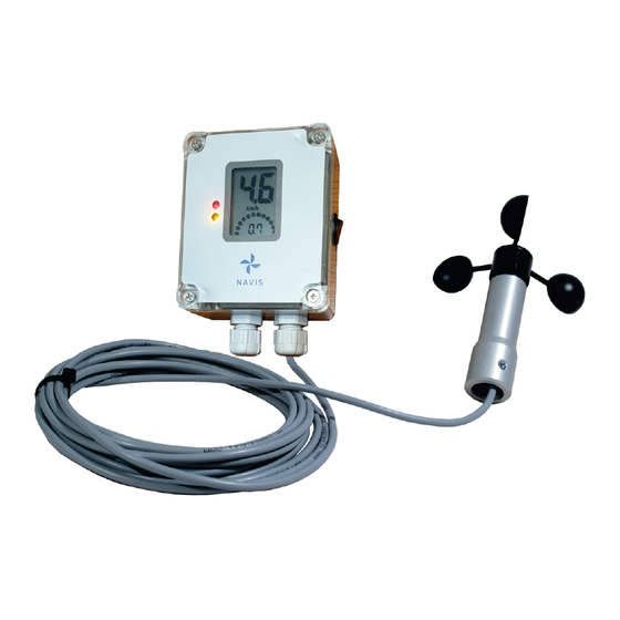
ANEMOMETER WITH ALARMS
Model: Y210/WS
MANUAL
Advertisement

Related Manuals for NAVIS Y210/WS


Summary of Contents for NAVIS Y210/WS
- Page 1 MANUAL PREFACE Thank you for purchasing the Navis anemometer. This manual provides information for the best performance and safe application of the anemometer display unit. Read this manual carefully before starting the installation. Keep this manual after installation for future reference.
- Page 2 WARRANTY (LIMITED) The warranty period of NAVIS products is one year after the date of purchase. During the limited warranty period any defective product will be repaired or replaced with a comparable product without charges. The claimed product will be repaired or replaced only when returned to the store where it was purchased together with original invoice.
Need help?
Do you have a question about the Y210/WS and is the answer not in the manual?
Questions and answers