Table of Contents
Advertisement
Quick Links
The Comepi safety limit switches are devices designed and made in
compliance with the interna�onal IEC regula�ons and the EN European
standards.
They can be used on machines where danger condi�ons may last for a
certain period of �me a�er the stop signal and for building safety systems
in compliance with standard ISO14119. Being a protec�on equipment for
operators, its incorrect installa�on or tampering can damage people,
even seriously.
The device installa�on must be carried out according to the regula�ons in
force by authorized staff only.
Make sure the switch works properly before star�ng the machine and
periodically check the correct opera�on of the equipment.
Installa�on precau�ons
Before star�ng the machine, check the proper opera�on of the safety
system.
Periodically check the correct opera�on of the device.
The device installa�on must be carried out by authorized and qualified
staff only.
The device use must be limited to the applica�ons mee�ng the regula-
�ons requirements.
The device installa�on and the safety system design must be carried out
only by people knowing the regula�ons in force.
The device installa�on and the safety system design must be carried out
in compliance with the regula�ons in force.
In case of doubts or special applica�ons, please contact COMEPI Technical
Support.
Do not install in dusty or dirty places.
During installa�on and opera�on, it is fundamental to prevent dust and
dirt from entering the opening when the start key is not inserted.
Before any pain�ng opera�on, cover the openings and the iden�fica�on
label.
Do not install in places where there are flammable dusts or gases.
Do not install in places with strong vibra�ons; impacts and vibra�ons can
prevent the switch correct opera�on.
Do not remove and install again the star�ng head: improper installa�on
may lead to malfunc�ons.
Possibility of disassembling, rota�ng and reassembling the drive head:
the opera�on, if performed incorrectly, could lead to malfunc�on.
(follow the instruc�ons on page 2)
Use only proper actuators supplied by COMEPI, suitable for the model
used; otherwise warranty could be void.
Install the actuator in a suitable way, so that it does not harm the
operator when the door is open.
If the microswitch is damaged or worn, replace the whole device to
ensure safety.
If the actuator is damaged or worn, replace it.
Replace the equipment a�er exceeding the mechanical durability limit.
Technical data
Casing
Room temperature during operation
Environmental designation
Protection against electrical
shocks
Degree of protection IP
Rated insulation voltage Ui
Use categories according to
UL508
Connecting terminals
Dimensions of connecting cables*
*Only use copper conductors 60/70°C, AWG14-18, stranded and solid conductor. Terminals maximum tightening torque 0.8Nm
The CE declaraiton of this product is available in the download sec�on of website www.comepi.it or by wri�ng to the following email address: tecnico@comepi.it
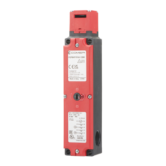
DDC 12 – Electromagne�c switches with separate actuator series FEP
Use instructions – Electromagnetic safety limit switch
Technopolymer casing
Rated impulsive withstand voltage Uimp
-25°C ... +70°C
Conventional thermal current Ith
Type-1 enclosure
Opera�onal current AC-15
Class II (thermoplastic casing)
Operational current DC-13
IP65 (plastic casing)
Maximum switching frequency
250V
Load factor
A300 – Q300
Resistance between contacts
Screws M3 with cable clamp
Terminal marking
Mechanical durability
0.34 ... 1.5 mm²
B10d
During wiring, keep load under the value of the use category.
Check that safety contacts are connected to a protec�on fuse.
Before reaching the switch contacts, make sure the device is not
supplied with power.
Tighten the screws with a �ghtening torque not higher than 0.5Nm.
The device must not be disposed of following special procedures, just
comply with the regula�ons in force in the country where the device is
used.
Use limits
Use the switch complying with the regula�ons in force within its
opera�on limits and following the instruc�ons.
The manufacturer is not to be held responsible for damages if: the device
was not used properly, instruc�ons were not followed, assembly and
maintenance opera�ons were carried out by unauthorized or unskilled
staff, func�onal tests were omi�ed.
This device complies with the following Direc�ves:
Low Tension Direc�ve 2014/35/EU According to standard EN 60947-5-1
Machinery Direc�ve 2006/42/EC According to standard EN ISO 14119
Direc�ve RoHS 2002/95/EC
Approvals
cULus according to standard UL508 – IMQ according to EN 60947-5-1
(for the complete list of the cer�fied products, please contact COMEPI
Technical Support).
Use and opera�on examples
This kind of device is typically used to ensure the operator's safety
on machines where a danger condi�on can last a certain �me a�er the
stop condi�on has been enabled on the machine, for example due to
iner�a of some mechanical moving parts, or to the presence of parts with
high temperature or pressure.
This device, if used singularly, is not suitable for machines where the
operator can completely enter a fenced area, because an accidental
closure of the fence may occur a�er the operator had entered this area.
To test the proper opera�on of the equipment, check the correct
inser�on of the actuator into the head opening and close the guard
star�ng the machine.
In these condi�ons it shall not be possible to open the guard.
When the machine is stopped and the protec�on disabled, the machine
shall not start.
Safety warnings
Safety switches protect operators.
An incorrect installa�on as well as the tampering of the device and of its
safety system can cause even extremely dangerous situa�ons.
Never bypass or tamper with the device.
In order to avoid any tampering a�empt, it is advisable for the installer to
mount the device in a place that cannot be easily reached by
unauthorized staff, even using physical barriers or other means to make
tampering difficult.
010 ISTR 03 SC 1221-02
2,5 kV
10A
24V
10A
230V
4A
24V
4A
600 cycles/hour
0.5
25 mΩ
According to IEC 60947-5-1
1 million operations
4 million operations
Advertisement
Table of Contents

Related Manuals for COMEPI 010 ISTR 03 SC 1221-02


Summary of Contents for COMEPI 010 ISTR 03 SC 1221-02
- Page 1 *Only use copper conductors 60/70°C, AWG14-18, stranded and solid conductor. Terminals maximum tightening torque 0.8Nm The CE declaraiton of this product is available in the download sec�on of website www.comepi.it or by wri�ng to the following email address: tecnico@comepi.it DDC 12 – Electromagne�c switches with separate actuator series FEP...
- Page 2 Dampet Swivel fold key flat key The CE declaration of this product is available in the download section of website www.comepi.it or by writing to the following email address: tecnico@comepi.it DDC 12 – Electromagnetic switches with separate actuator series FEP...
- Page 3 Contact numbering The CE declaraiton of this product is available in the download section of website www.comepi.it or by writing to the following email address: tecnico@comepi.it DDC 12 – Electromagnetic switches with separate actuator series FEP...
- Page 4 010 ISTR 03 SC 1221-02 Definition of electrical contacts The CE declaraiton of this product is available in the download section of website www.comepi.it or by writing to the following email address: tecnico@comepi.it DDC 12 – Electromagnetic switches with separate actuator series FEP...
Need help?
Do you have a question about the 010 ISTR 03 SC 1221-02 and is the answer not in the manual?
Questions and answers