Table of Contents
Advertisement
Quick Links
APPLICATIONS
•
Silo/Tank weighing
•
Batch weighing
•
Platform scales
FEATURES
•
Digital high accuracy design
DIP switches)
•
Excitation for up to 10 x 350Ω loadcells
•
6 or 4 wire loadcell connection
•
Update rate 100 times per second
•
4-20mA output
•
Modbus communications (independent
RS232 and RS485 ports)
•
USB Host & Device (memory stick & PC)
•
Field software upgrades
•
12-24Vdc power supply
•
Overall accuracy better than 0.01%
•
Totalising
•
Peak reading
•
Rate of change
(flowrate)
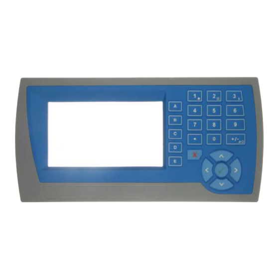
MD2,MP2 INDICATOR
•
IP54 Facia
•
2.8" (70mm) colour LCD
•
320 x 240
pixels
•
Polyester film tactile keypad
•
4-20mA output, 1 digital input & 2 digi-
tal outputs
MO3 I/O for MP2
•
4 Digital inputs
•
4 Digital outputs
•
4-20mA input (or 0-10V)
•
4-20mA output
MD1,MP1 INDICATOR
•
IP65 Facia
•
4.3" (109mm) colour LCD
•
480 x 272
pixels
•
Silicone tactile keypad
MT1 TRANSMITTER
•
Size 136 x 66 x 50mm
•
Optional removable P-Module holds cali-
bration settings
MT3 TRANSMITTER
•
Size 136 x 66 x 50mm
MR1 I/O
•
Size 136 x 66 x 30mm
•
8 Digital inputs
•
8 Digital outputs
•
4-20mA input (or 0-10V)
•
4-20mA output x 2
•
Pulse output
MW61A_IM_ALL_SV6.09d_en
Weigher Instrument
INCLUDES
Installation
•
Setting up principles
•
Setup Summary
•
I/O Function Table
•
Operation
•
Alarms
•
(no pots or
APPLIES TO
MW61A - Weigher P-Module
•
MT1,MT3 - Transmitters
•
MD1,MD2 - Display
•
MP1,MP2 - Processor
•
MR1 - Remote IO
•
Software v6.09 onwards
•
Instruction Manual ALL
MD1,MP1
MT1
MR1
EMC INDUSTRIAL GROUP LTD
MW61A
MD2,MP2
MT3
Advertisement
Table of Contents

Related Manuals for EMC ModWeeihg MW61A

Summary of Contents for EMC ModWeeihg MW61A
- Page 1 Size 136 x 66 x 50mm MR1 I/O • Size 136 x 66 x 30mm • 8 Digital inputs • 8 Digital outputs • 4-20mA input (or 0-10V) • 4-20mA output x 2 • Pulse output MW61A_IM_ALL_SV6.09d_en EMC INDUSTRIAL GROUP LTD...
- Page 2 MW96 Weighfeeder Instrument Technical Information Instruction Manual COPYRIGHT © 2019 by EMC Industrial Group Ltd 56 Tarndale Grove, Albany, North Shore, Auckland 0632 PO Box 101 444 North Shore, Auckland 0745, New Zealand Telephone +64-9-415 5110, Facsimile +64-9-415 5115 E-mail sales@emc.co.nz Web http://www.emc.co.nz...
-
Page 3: Table Of Contents
EMC INDUSTRIAL GROUP LTD Features Contents Measuring Range INTRODUCTION ............5 Display Resolution Features Calibration Basic Calibrate Loadcell Inputs Internal Signals SETUP – MW61A WEIGHER ........24 Outputs Basic Settings Communications & Display Engineering units IO Summary Enter weighing units... - Page 4 EMC INDUSTRIAL GROUP LTD Features Information & Resets Display Product Information Keys Reset settings Operator Menu Other display settings Actions Settings I/O Function Table Alarm menu Modbus Access OPERATION............43 MW61A_IM_ALL_SV6.09d_en 4/47...
-
Page 5: Introduction
EMC INDUSTRIAL GROUP LTD Features INTRODUCTION Features Basic Units & Resolution The units for each variable type (weight etc.) can be selected from a list of metric and imperial units. The resolution of each variable type can be adjusted, this alters the count by e.g 100kg displayed in 0.2kg increments. -
Page 6: Communications & Display
EMC INDUSTRIAL GROUP LTD Specifications Digital Outputs OUTx The digital outputs are programmable to operate from any internal signal. These signals include the digital input states, status conditions (running, paused etc) and any fault conditions that are detected. This makes it easy connect into other systems. -
Page 7: Analog Input Ai2
EMC INDUSTRIAL GROUP LTD Specifications Signal processing rate 100 Hz (response time setting≤ 0.5 s) Input sensitivity 0.5 µV/division maximum Zero range ±3 mV/V (±15 mV) Zero drift ±0.02 µV+0.0005 % of deadload/°C typical Span drift ±0.0005 %/°C typical Non-linearity ‹0.002 % of FS... -
Page 8: Installation
EMC INDUSTRIAL GROUP LTD Dimensions INSTALLATION The instrumentation must be mechanically installed and then the electrical connections made. The im- portant electrical connections are as follows. Power supply connections: 24Vdc fused or current limited to 5A. Communications: A shielded cable is recommended to connect units together with COM2. It can extend up to 500m. -
Page 9: Connection Diagram - Mp2
EMC INDUSTRIAL GROUP LTD Connections The display is normally located to suit an operator. The transmitter can be located in the field to reduce field wiring or can be located with the display for a more conventional approach. The I/O can conveniently be situated on a DIN rail in a cabinet. -
Page 10: Connection Diagram - Mp1
EMC INDUSTRIAL GROUP LTD Connections Connection Diagram – MP1 Keep all wiring separated POWER SUPPLY Power/COM2 from mains wiring +24V LOADCELL(s) optional sense for 6 wire BELT SPEED TACHO connection −D Use shielded cable where Loadcell indicated output −EX/0V COM1... -
Page 11: Connection Diagram - Mt1
EMC INDUSTRIAL GROUP LTD Connections Connection Diagram – MT1 MD1,MD2 POWER SUPPLY Power/COM2 Keep all wiring separated +24V COM1 from mains wiring. RJ12 −D Use shielded cable where indicated. LOADCELL(s) optional sense for 6 wire connection to PC/PLC Loadcell 1... -
Page 12: Connection Diagram - Mt3
EMC INDUSTRIAL GROUP LTD Connections Connection Diagram – MT3 MD1,MD2 POWER SUPPLY Power/COM2 Keep all wiring separated +24V COM1 from mains wiring. RJ12 −D Use shielded cable where indicated. LOADCELL(s) optional sense for 6 wire connection to PC/PLC Loadcell 1... -
Page 13: Multidrop Systems
EMC INDUSTRIAL GROUP LTD Connections Loadcell 1 1 −E −EX/0V +SIG −SIG −S +SEN −SEN −E LOADCELL(s) −S optional sense for 6 wire connection Loadcells Wired to Junction Box 1 −E For best accuracy use a 6-wire connec- −S tion to controller −E... -
Page 14: Setting Up
EMC INDUSTRIAL GROUP LTD Setup Setting the COM1 Modbus Address Before a multidrop system will operate, the addresses in each of the ModWeigh units will need to be set differently. This can be done by wiring a link or resistor to the ADS terminal where available. See the table on the connection diagram. -
Page 15: Keypad
EMC INDUSTRIAL GROUP LTD Setup Basic Settings The basic settings are settings which generally must be set first and often affect other settings through the controller. For example, they set the engineering units and measuring range for the application. Inputs The inputs are settings and calibration which effect the basic inputs signals. -
Page 16: Displaying The Setup Menus
EMC INDUSTRIAL GROUP LTD Setup SETUP key Press to view the setup menus. ALPHANUMERIC keypad Used to enter numerical data values. UP and DOWN keys Use these keys to move up and down a menu, or to increase or decrease a setting when editing is en- abled. -
Page 17: To Adjust A Setting
EMC INDUSTRIAL GROUP LTD Setup Service Service menu contains all standard settings as well as settings for advanced configuration and diagnos- tics. Use this menu if there are special application requirements, or if special diagnostics are required. This menu includes the Factory settings, for which certified equipment is required. These settings are not documented in this manual, contact the factory for further information. -
Page 18: Macros
EMC INDUSTRIAL GROUP LTD Macros Macros A macro is a list of numbers representing text characters and instructions codes. Each number is edited separately, and is entered either as a number using the numeric keys, or as an text character using the letter keys much like a cell phone. - Page 19 EMC INDUSTRIAL GROUP LTD Macros Register Instructions MENU ‹argument› ‹argument› action start_menu next_quick next_service next_factory next_altered MACRO ‹argument› ‹argument› action start_macro next_macro next_ altered _macro Print Instructions PRINT_VALUE “format” is an ASCII format code of the form CcDdBb. c is the column width, d is the number of decimal places and b is the count by.
-
Page 20: Adjusting A Macro
EMC INDUSTRIAL GROUP LTD Macros Looping and Control Instructions DRIVE_BIT ‹bit› value test IF ‹condition› 1-150 See I/O Function Table IF_EVENT ‹event condition› value test value test VALUE›=0 VALUE_ALTERED AND ‹condition› VALUE›0 VALUE_NOT_ALTERED OR ‹condition› VALUE=0 VALUE_VIEW_ONLY ELSE VALUE‹›0 DEC_temp1=0 END_IF VALUE‹0... -
Page 21: Software Updating
EMC INDUSTRIAL GROUP LTD Macros Shows which numeric keys are used to enter upper case let- ters. Gives a guide to the range of values for text, register instruc- tions, print instructions, calculation instructions and looping & control instructions. Sequence of quick-keys used to reach this macro. Not editable. The left-most digit identi- fies the current menu as follows: 1 for Quick setup, 2 for Main setup, 3 for Service setup, and 4 for Altered setup. -
Page 22: Update With A Pc
EMC INDUSTRIAL GROUP LTD Settings Update with a PC Windows™ PC ModWeigh unit Updating Procedure Copy the ModUpdater program (e.g. ModUpdaterv6.01r10.exe) onto a PC. The name contains the version number of the software to be installed. Before starting, it may be advisable to record the settings in the unit if you wish to restore these after updating. -
Page 23: Initial Setup
EMC INDUSTRIAL GROUP LTD Initial Setup Step Quick Keys Set the digital output terminal functions 243x INFORMATION, RESETS & FINAL CALIBRATION Set key locks or customise the display 256xx Initial Setup Before calibration can be done, the system integrators will need to have completed all the wiring and you will need suitable test weights. -
Page 24: Setup - Mw61A Weigher
EMC INDUSTRIAL GROUP LTD Basic Settings SETUP – MW61A WEIGHER Basic Settings Basic Settings Inputs Internal Signals Outputs Communications & Display Information, Resets & Final Calibration Engineering units These settings affect the engineering units that will be used for many other settings. The engineer- ing units can be changed at any time. -
Page 25: Weight Change Constants
EMC INDUSTRIAL GROUP LTD Inputs Weight change constants Q2181 control function 8088, g0 The control functions sets whether the flowrate is measured by weight loss (decreasing weight) or weight gain (increasing weight). Set to 0 for weight loss or to 1 for weight gain. -
Page 26: Loadcell Input (Vessel Weight)
EMC INDUSTRIAL GROUP LTD Inputs Loadcell input (vessel weight) Input settings * Q22311 AI1 response time [0.04 to 32] 8120, g1 0.50 s The response time for the weight signal. A larger value will help reduce variations in the weight reading caused by vibrations or movement on the weighing system. -
Page 27: Calibrate Using Loadcell Specifications
EMC INDUSTRIAL GROUP LTD Inputs Calibrate Using Loadcell Specifications The loadcell can be calibrated using the loadcell(s) capacity and sensitivity supplied by the manufac- turer. Using this method avoids the need to load and unload test weights onto the weighing system. If the system has already been calibrated using test weights, the actual dead load and loadcell sensitivity are displayed. -
Page 28: Internal Signals
EMC INDUSTRIAL GROUP LTD Internal Signals Q2242 AI2 current high 8142, g2 20.000 mA This is the high point of the analog signal (when using the current input) within the range 0 to 20 mA (typically set this variable to 20 mA). -
Page 29: Flowrate
EMC INDUSTRIAL GROUP LTD Internal Signals Q23126 zero weight 8220 kg,t,g Displays the amount of weight that has been zeroed out since the last zero calibration. Weight motion motion detection band (set to 0 to disable) [0 to 50] Q23131 8230, g5 3.0 divs... -
Page 30: Events/Alarms/Faults
EMC INDUSTRIAL GROUP LTD Internal Signals Limit 3 Q23531 limit 3 source (modbus address of signal) 8340, g7 Q23532 limit 3 mode 8344, g7 fill control = 4 Q23533 limit 3 delay 8342, g7 0.00 s Q23534 setpoint 3H 8334... -
Page 31: User Data
EMC INDUSTRIAL GROUP LTD Outputs Memory Recall/Store The following 3 settings are used to recall or store a group of settings and to set a name for each group. The groups are numbered from 0 to 19. Unless the memory usage is disabled, these settings will appear in the operator’s MENU, accessed by pressing the MENU key. -
Page 32: Analog Output 2 (Gross Weight)
EMC INDUSTRIAL GROUP LTD Communications & Display Q2416 AO1 current (can override output signal) 8800, g10 Displays AO1 current. This setting may be altered to temporarily manually set the output current. This is useful to test the analog output. The output will return to normal after you exit from the settings. -
Page 33: Comms Port 2 - Rs485
EMC INDUSTRIAL GROUP LTD Communications & Display Q2512 COM1&2 modbus address [1 to 30] 8592, g12 modbus address. Q2513 COM1 handshake enable [0=disable, 1=enable] 8584, g12 When set to 1, hardware handshaking is enabled. Set to 0 to disable hardware handshaking. -
Page 34: Printing & Macros
EMC INDUSTRIAL GROUP LTD Communications & Display Printing & Macros Q2551 print settings and macros 8922, g13 Used to start a print out of the settings or of the macros. Select the number of the print out required. number printout... -
Page 35: Display (Md1,Md2,Mp1,Mp2)
EMC INDUSTRIAL GROUP LTD Communications & Display Q25543 print total key subroutine 2200, g13 A subroutine used by the print total key macro. Q25544 settings subroutine 2300, g13 A subroutine used by the print settings macro. Q25545 macros subroutine 2400, g13 A subroutine used by then print settings macro. - Page 36 EMC INDUSTRIAL GROUP LTD Communications & Display Q25611 acquire zero lock 8620, g4 Q25612 acquire tare lock 8622, g4 Q25613 toggle net/gross mode lock 8624, g4 Q25614 reset tare weight lock 8626, g4 Q25615 totalise weight lock 8628, g4 Q25616...
- Page 37 EMC INDUSTRIAL GROUP LTD Communications & Display Value Display Description hide units hide net/gross icon hide tare icon hide zero icon hide zero band icon hide motion icon hide setpoint 1 icons hide setpoint 2 icons hide gross weight bar graph...
-
Page 38: Usb
EMC INDUSTRIAL GROUP LTD Info, Resets & Final Cal Signal 3 Q256731 signal 3 source 18004 Q256732 signal 3 name 4200 Q256733 signal 3 type 18014 Signal 4 Q256741 signal 4 source 18006 Q256742 signal 4 name 4300 Q256743 signal 4 type... -
Page 39: Reset Settings
EMC INDUSTRIAL GROUP LTD Basic Settings Q2618 MO3 serial number 8866 Displays the serial number of the MO3 option if fitted. Reset settings Q2631 reset loadcell calibration (1=reset to defaults) 8950 Set to 1 to reset the loadcell calibration to the default. -
Page 40: Communications & Display
EMC INDUSTRIAL GROUP LTD Communications & Display Communications & Display Comms port 1 – RS232 Q92511 COM1 baud rate (8 data, no parity, 2 stop) 8580 19200 Q92512 COM1&2 modbus address [1 to 30] 8592 Q92513 COM1 handshake enable [0=disable, 1=enable]... - Page 41 EMC INDUSTRIAL GROUP LTD I/O Function Table Input Functions (edge sensitive ) CONTROL1 acquire zero 0 Ϯ The control1 register contains 16 level sensitive input signals. This register has 5 acquire tare 1 Ϯ control sources which are combined together.
- Page 42 EMC INDUSTRIAL GROUP LTD I/O Function Table Output Functions limit 1 output limit 2 output limit 3 output OUT0 OUT9 MO3 fitted disable macros MR1 connected Output Functions This register hold the state of inputs IN1 to IN8 and outputs OUT1 to OUT8.
-
Page 43: Modbus Access
EMC INDUSTRIAL GROUP LTD Display Input Functions (level sensitive Π or edge sensitive ) Modbus Access The communications ports of the ModWeigh Controllers (COM1 and COM2) use Modbus protocol. This can be used to access any data value and any user setting. -
Page 44: Keys
EMC INDUSTRIAL GROUP LTD Keys Identification of selected unit. Press SELECT ( ) to view and select another unit from list of units connected. Alarm Symbol flashes when an alarm is present. Main display bar graph. Shows the displayed weight. The indicators show the positions of the low and high setpoints. -
Page 45: Operator Menu
EMC INDUSTRIAL GROUP LTD Keys setup menu The setup menu is used to calibrate and setup the system. Refer to the Instruction Manual. Operator Menu The operator menu allows selection of one of several actions or settings. Soft key icon for this function. See Actions and Settings below for a description of these icons. -
Page 46: Settings
EMC INDUSTRIAL GROUP LTD Keys print total Press this key to print the totalised weight. reset peak weight Press this key to reset the peak weight. reset total weight Press this key to reset the totalised weight. acquire zero Press this key to zero the weight display. - Page 47 EMC INDUSTRIAL GROUP LTD Keys Alarms Alarm Comments AI1 < -4mV/V: faulty loadcell or wiring AI1 > 4mV/V: faulty loadcell or wiring weight fault weight too low weight too high no sense voltage: faulty loadcell or wiring user fault 1...
Need help?
Do you have a question about the ModWeeihg MW61A and is the answer not in the manual?
Questions and answers