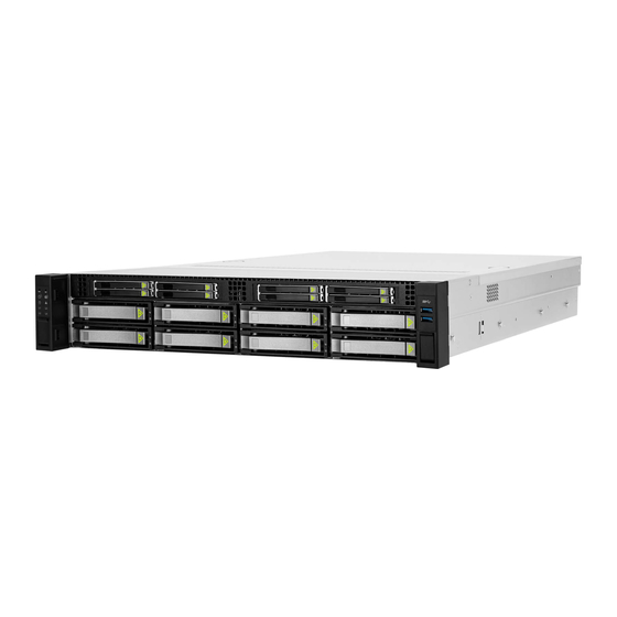
Summary of Contents for InWin IW-RS216-07
- Page 1 IW-RS216-07 HYBRID BACKPLANE USER MANUAL P/N : 2RAKVI009200 Model:IW-RS216-07 15mm 2BAY HYBRID BACKPLANE-V MODULE Version : V1.0 Model : IW-RS216-07 15mm Hybrid Backplane User Manual PAGE 1 OF 12...
- Page 2 Revision History Version Changes Date V1.0 Official Release 2021/05/25 Model : IW-RS216-07 15mm Hybrid Backplane User Manual PAGE 2 OF 12...
-
Page 3: Table Of Contents
Connector/ LED Indicators....................6 Connector Pin Definitions..................... 7 Hardware Specification ................. 8 LED Behavior ....................9 Disk Bay LED........................9 Firmware Upgrade ..................11 Model : IW-RS216-07 15mm Hybrid Backplane User Manual PAGE 3 OF 12... -
Page 4: Overview
Overview InWin backplanes (without Expander) are high performance and cost effective solution for supporting Intel Purley platform by adding NVMe support. The passive backplanes support state-of-the-art SAS3 12Gbps HDD/SSD and also backward compatible with SAS 6Gbps, SATA 6Gps and SATA 3Gps HDD/SSD. The backplane supports NVMe SSD through OcuLink x4 connectors. -
Page 5: Mechanical
Mechanical Model : IW-RS216-07 15mm Hybrid Backplane User Manual PAGE 5 OF 12... -
Page 6: Connector Locations And Led Indicators
Connector/ LED Indicators. Location SAS/U.2 Drive Number DISK1/ DISK2 SATA/SAS Disk or NVMe SSD #1/#2 Location Hard Drive Power/Activity/Failure/Locate LEDs PD1/PD2 DISK1/DISK2 Power LED D1/D2 DISK1/DISK2 Activity/Failure/Locate LED Model : IW-RS216-07 15mm Hybrid Backplane User Manual PAGE 6 OF 12... -
Page 7: Connector Pin Definitions
Definition +12V 2 & 3 Ground Firmware Programming Connector PIN # Definition PIN No# Definition ICE_CLK ICE_DATA #Key ICE_RST Ground P2.0 2-Pin Connector PIN # Definition LINK_CLK LINK_DAT Model : IW-RS216-07 15mm Hybrid Backplane User Manual PAGE 7 OF 12... -
Page 8: Hardware Specification
SFF-8639 U.2 68PIN Connector (DISK1~DISK2) for SATA/SAS3 Disk or NVMe SSD. P4.2mm Disk Drive Power Connector*1 (PW1) JD1 MCU Programming Header for Programming MCU Firmware S1 DIP Switch for Backplane Master/Slave Selection. Model : IW-RS216-07 15mm Hybrid Backplane User Manual PAGE 8 OF 12... -
Page 9: Led Behavior
When SGPIO is disabled, the RED LEDs (for Locate and Fail) do not behave while the GREEN LEDs (for Activity) behave according to the signal from P11 (READY LED) of the disk connectors. Model : IW-RS216-07 15mm Hybrid Backplane User Manual PAGE 9 OF 12... - Page 10 NVMe3 connector’s sideband I2C bus and …etc. System Alarm LED There is a FAIL LED (DB2) design on the Backplane to indicate Over-Temperature for indicating system fault. Model : IW-RS216-07 15mm Hybrid Backplane User Manual PAGE 10 OF 12...
-
Page 11: Firmware Upgrade
1. Require Nuvoton ARM Cortex-M0 programming tool. Nu-Me or Nu-Link and install Nuvoton ICP Programming tool software. 2. Connect Nu-Link USB end to a host and the SWD end to Backplane ICE connector for each MCU. Model : IW-RS216-07 15mm Hybrid Backplane User Manual PAGE 11 OF 12... - Page 12 3. Make sure device is connected and select the binary file being programmed and then click on Start button to program firmware. 4. Please refer to http://www.nuvoton.com/resource- files/NuLink_Adapter_User_Manual_EN_V1.01.pdf for more details. Model : IW-RS216-07 15mm Hybrid Backplane User Manual PAGE 12 OF 12...


Need help?
Do you have a question about the IW-RS216-07 and is the answer not in the manual?
Questions and answers