Table of Contents
Advertisement
Advertisement
Table of Contents

Related Manuals for Tufner T909


Summary of Contents for Tufner T909
- Page 1 T909 User’s Manual...
-
Page 2: Table Of Contents
TABLE OF CONTENTS SAFETY PRECAUTIONS ............PREPARATION & SET UP ............FEATURES ................SPECIFICATIONS ..............POWER SUPPLY ..............DISPLAY AND KEY DESCRIPTION ........OPERATING INSTRUCTIONS ..........CALIBRATION PROCEDURE ..........INDICATOR PARAMETER SETTINGS ........CONNECTORS ............... TROUBLESHOOTING ............ -
Page 3: Safety Precautions
SAFETY PRECAUTIONS Please read and follow all the instructions before using the unit. Calibration, inspections, and maintenance shall be performed by professionals Make sure the indicator is on a stable surface. DO NOT disassemble or modify unit. DO NOT exceed the rated load limit of the unit. DO NOT use this product if there are any signs of damage. -
Page 4: Features
FEATURES Main Features LED display Weighing units lb/kg or lb/kg/g/oz/lb-oz (only on upgraded model) Gross/Tare/Pre-Set Tare/Zero Multiple Hold functions Overload / Underload indication Configurable with multiple printers Splash proof keyboard and display Connects to a Remote Display/Scoreboard Power saving mode Ability to modify gravity based on different geographical locations RS232 output Optional dual load cell ports... -
Page 5: Specifications
SPECIFICATIONS INDICATOR MEASUREMENTS 8.2 in 8.3 in 2.3 in POWER SUPPLY AC Adapter If the indicator is powered with an adapter, plug the adapter directly into the “DC” pin located at the bottom of the indicator. It is recommended to plug into a wall outlet to avoid interference with wirings. -
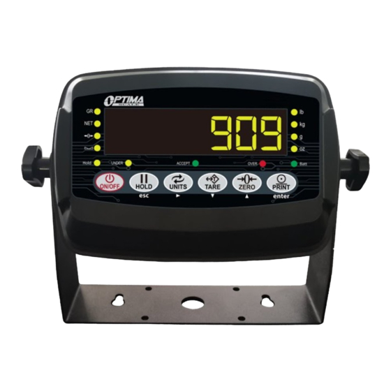
Page 6: Display And Key Description
LIGHT INDICATION AND KEYPAD FRONT VIEW 1. LIGHT INDICATION lb: ON when the weight unit is pound [lb] kg: ON when the weight unit is kilogram [kg] g: ON when the weight unit is gram [g] oz: ON when the weight unit is oz [oz] Batt: GREEN when the battery is fully charged;... -
Page 7: Operating Instructions
BOTTOM VIEW RS-232 PORT DC POWER LOAD CELL LOAD CELL: Port for connecting the scale. RS-232 PORT: Serial interface port. (printer, second display, PC, etc.) DC POWER: Port for DC power. (DC 9V adapter available) OPERATING INSTRUCTIONS Power On Turn on the power by pressing the power button for 2 seconds. Once it is on, the unit begins to auto-check and count down from 0-9 before entering the weighing mode Note: Anything on the scale before powering on will automatically be tared out. -
Page 8: Calibration Procedure
Hold There are 3 different hold functions you can choose from in the C11 parameter 1. Peak Hold: Grabs the highest weight (for materials testing, ie. tension and pulling force) Press the HOLD key then add weight to the scale The indicator will show the highest weight it recorded and hold it on the screen until a higher weight is placed on the scale 2. - Page 9 Calibration Menu Turn on the scale by holding ON/OFF for 2 seconds. Press HOLD and PRINT enter together to access the setup menu. If done correctly, the display should now show Press PRINT enter to access the C1 channel. The display should show # ].
- Page 10 23. Enter the calibration weight value you will use (at least 10% of max capacity you set in C04 by using UNITS to move the cursor right, and TARE and ZERO move the values down and up.) 24. Place the calibration weight you have on the empty scale and press PRINT enter. 25.
-
Page 11: Indicator Parameter Settings
INDICATOR PARAMETER SETTINGS The parameter settings menu has a calibration section (C01 to C07 explained above) and a parameter settings section (C08 and up). To access the calibration section the seal switch (located at one corner of the PCB) must be OFF. - Page 12 Function Parameter Settings/Options 0 = do not restore Restore Default Settings 1 = restore to default settings 0 = turn off warning tone Warning Tone 1 = turn on warning tone 0 = turn off auto power off 10 = power off automatically if no change within 10 minutes Automatic Power Off 30 = power off automatically if no change within 30 minutes...
- Page 13 Function Parameter Settings/Options 0 = no initial zero setting 1 = ±1% max capacity 2 = ±2% max capacity Initial Zero Range 5 = ±5% max capacity 10 = ±10% max capacity 20 = ±20% max capacity 100 = ±100% max capacity 0= turn off zero tracking 0.5 = ±0.5d d = division...
- Page 14 Function Parameter Settings/Options yy.mm.dd mm.dd.yy Print Time and Date dd.mm.yy yy.mm.dd Analog Output Setting 0 - 5V output 4 - 20mA output Calibrate Current 4 - 20mA current 0 = turn off relay output 1 = turn on relay output function 1 Relay Output Setting 2 = turn on relay output function 2 3 = Reserved menu...
- Page 15 Table 3. Default Parameter Settings Function Parameter Default Setting Weighing Unit Decimal Setting Graduation Setting Maximum Capacity 100000 Zero Calibration Calibration Restore Default Warning Tone Automatic Power Off Power Saving Mode Hold Function Unit Conversion Upper Limit Alarm 000000 Lower Limit Alarm 000000 Inner Code Display Set Date...
-
Page 16: Connectors
CONNECTORS 1. Load cell connection The indicator can work with up to 8 load cells of 350Ω Either 4 wire or 6 wire load cell connection Please contact us directly if you have other special needs for your applications There are two connection methods between the load cell and indicator Quick Disconnect as shown below: FIGURE 2: QUICK DISCONNECT CONNECTION DIAGRAM Hardwire (Using Inner Terminal Block Connection:... - Page 17 Table 4. Wiring Color Code Signal Name Color Code Description +Exe/ +EX Positive excitation voltage to load cell +IN / +SIG GREEN Positive output signal from load cell HD / SHLD YELLOW/THICK BLACK Shield Wire -IN / -SIG WHITE Negative output signal from load cell -EXC / -EX BLACK Negative excitation voltage to load cell...
- Page 18 Remote Display Continuous Sending Mode (C18=1) For use with a Scoreboard/Remote Display Note: Baud Rate must be set to 1200 (C19 = 0) Output Continuous Format State A Bits0,1,2 Decimal point position XXXXXX0 XXXXXXX XXXXX.X XXXX.XX XXX.XXX Bits3,4 Division State B BitsS function Bits0...
- Page 19 Print Mode (C18 = 2) For printing on a non-adhesive ticket printer. Parameters 16, 17, 30, & 42-45 all effect your ticket print out. Normal weighing ticket printout example: Date: 05/01/2017 Time: 11:30:52 Net: 25.6lb Tare: 10.3lb Gross: 35.9lb Command Request Mode (C18=3) In this mode, the indicator can receive ASCII commands as listed below Command Name...
- Page 20 PC or Remote Display Continuous Sending Mode (C18=5) Print to Adhesive Label Printers (C18=5) & (C18=6) Printing formats: Date: 05/01/2017 Date: XX.XX. XX (yy.mm.dd) Time: 11:30:52 Time: XX.XX.XX (hh.mm.ss) Net: 25.6lb 6.00kg (net weight) Tare: 10.3lb 2.88kg (tare) TARE Gross: 35.9lb GROSS 8.88kg (gross weight)
-
Page 21: Troubleshooting
TROUBLESHOOTING Issues/Error Codes Possible Causes Suggested Actions Scale does 1. Loose power cord 1. Ensure the power cord is plugged in not turn on 2. Outlet is defective 2. Ensure the power source works. Test the power source by connecting a different appliance to the same outlet to check if it’s operational. - Page 22 1. Calibration is no good 1. Ensure scale is leveled 2. Cables are not connected 2. Check load cell connection nnnnnnn properly 3. Check load cell input and output 3. Load cell is defective resistance 4. If the above actions don’t work, try the following instructions: •...
- Page 23 1. Check cables for any indentations, crimps, or cuts. Err6 Exceed Zero Range 2. Check your scale for damages. 3. Try calibration first Press and hold the HOLD and PRINT button at the same time for 3 seconds to get into calibration mode. C01 should appear. 4.
Need help?
Do you have a question about the T909 and is the answer not in the manual?
Questions and answers