Table of Contents
Advertisement
Quick Links
Original Operating Instructions
Original Operating Instructions
Original Operating Instructions
Flame Amplifier
Type:
Type:
Document:
Document
Mindermann GmbH
Eggerscheidter Strasse 57
D-40883 Ratingen Germany
Telephone +49 (2102) 9682-0
Facsimile +49 (2102) 9682-42
http://www.bfi-automation.de
3016
BA 3016 EN REV.4
BFI Automation
Advertisement
Table of Contents

Subscribe to Our Youtube Channel
Related Manuals for BFI Automation 3016


Summary of Contents for BFI Automation 3016
- Page 1 Original Operating Instructions Original Operating Instructions Original Operating Instructions Flame Amplifier Type: Type: 3016 Document Document: BA 3016 EN REV.4 BFI Automation Mindermann GmbH Eggerscheidter Strasse 57 D-40883 Ratingen Germany Telephone +49 (2102) 9682-0 Facsimile +49 (2102) 9682-42 http://www.bfi-automation.de...
-
Page 3: Table Of Contents
Weight - flame amplifier Space requirement Installation 4.6.1 19”-built-in housing (rack mount installation) 4.6.2 19”-built-on housing (wall mount installation) 4.6.3 Dimensions for 19”-built in/on housing Connection 4.7.1 Electrical connection 4.7.2 Terminal diagram 3016 4.7.3 Terminal diagram for using back panel 3001 Storage... - Page 4 Description Application Front plate Function Sensetivity adjustment Switch-Off time Option unit 5.6.1 Choice of sensitivity level II 5.6.2 DIP switch S1.2 5.6.3 Failure detection 5.6.4 Current output Wiring Galvanic decoupling Parallel connection of flame scanners Operation of the flame amplifier Connection of the flame amplifier Testing the flame amplifier Initial operation of the flame amplifier...
-
Page 5: General Aspects
General aspects General aspects Introduction These operating instructions are a helpful guide for ensur- ing the successful and safe operation of the flame ampli- fier. They contain important information on how to operate the system safely, correctly and efficiently. Observing the operating instructions will help to prevent hazards, reduce costs of repair and downtimes and increase the reliability and life of the device. -
Page 6: Warning Notes
General aspects Warning notes The following warning notes are used in these operating instructions: This warning level indicates an imminent hazardous situa- tion. If the hazardous situation is not prevented, this will result in death or severe injury. Follow the instructions that accompany this warning to prevent the risk of death and severe personal injury. -
Page 7: Copyright Protection
These operating instructions have to be treated as confi- dential. They may only be used by authorised staff. Ac- cess by third parties may only be granted upon written agreement of BFI Automation. All documents are protected in keeping with the German copyright law. -
Page 8: Warranty
• non-performance of specified maintenance work It is recommended that the operator of the device con- cludes a service contract with BFI Automation. This guar- antees that the device is regularly checked by our service staff and ensures that any required wearing and spare... -
Page 9: Obligation Of The Operating Company
General aspects Obligation of the operating company The flame amplifier may cause hazards if it is operated inappropriately or in an improper condition. The operating company is under the obligation to operate the machine in proper state only. The operating company has to secure hazardous areas that exist between BFI devices and the customer's own equipment. -
Page 10: Liability Disclaimer
BFI Automation for consequential damages. BFI Automation is liable for possible errors or omissions with the exclusion of additional claims entered into in the framework of the warranty obligations conceded to in the contract. -
Page 11: Declaration Of Conformity
This declaration of conformity of the European Communi- ties is the result of an examination of the TD Department of BFI Automation in accordance with the European Standards. If the system will be changed without our ap- proval this declaration will become invalid. -
Page 12: Address Of The Manufacturer
General aspects Address of the manufacturer BFI Automation Mindermann GmbH Eggerscheidter Strasse 57 D-40883 Ratingen Germany Tel. +49 (0) 2102 9682-0 Fax. +49 (0) 2102 9682-42 E-mail: info@bfi-automation.de Internet: www.bfi-automation.de... -
Page 13: Safety
Safety Safety Intended use The flame amplifier shall be used exclusively to detect flames in combination with a suitable flame scanner. The flame scanner and flame amplifier together constitute a complete flame monitoring system for burners with a ran- dom capacity and random fuels in single and multiple burner systems. -
Page 14: Requirements On Persons
Safety Requirements on persons Work on/with the device may only be performed by per- sons authorized to do so based on their training and quali- fication. Furthermore, such persons have to have been commissioned by the operating company. Do not allow any persons who are being apprenticed, educated, instructed or on a general training programme to work on the device without the constant supervision of an experienced person. -
Page 15: Safety Instructions
Safety Safety instructions The following instructions on accident prevention have to be observed when operating the flame amplifier. Only operate the device if it is in a proper state ! • Do not remove or disable safety devices. • Check for externally noticeable damage and defects prior to using the device ! Immediately notify the ap- propriate authority/person of any changes that occur (including changes in operating performance). -
Page 16: Safety Devices
Safety Safety devices 2.4.1 Fundamental aspects Check the safety equipment and locking devices on the device for safe operational condition. Only operate the device if all safety devices are present and enabled. The operating company or operator of the flame amplifier is responsible for the proper operation of the device. -
Page 17: Safety Instructions In Case Of Maintenance And Troubleshooting
• Operating and auxiliary materials as well as exchanged parts have to be disposed of in a safe and eco-friendly way. • Spare parts supplied by BFI Automation or approved of by BFI Automation only may be used. -
Page 18: Electrical / Electronic Devices
Safety 2.5.2 Electrical / electronic devices Danger to life caused by electrical current! Contact with live wires or components presents a danger to life ! Prior to any work on the electrical equipment, disconnect the flame monitoring system from the power supply net- work ! In keeping with the electrical regulations, work on electri- cal / electronic parts / components may only be carried... -
Page 19: Testing In Keeping With The German Workplace Safety Ordinance (Betrsichv)
Safety 2.5.3 Testing in keeping with the German Work- place Safety Ordinance (BetrSichV) In case of the coupling or installation of devices from vari- ous manufacturers or suppliers, the operating company has to carry out a precise test, prior to start-up, in keeping with the German Workplace Safety Ordinance (BetrSichV) in force and the applicable electrical regulations. - Page 20 Safety...
-
Page 21: Technical Data
Technical data Technical data General characteristic features • Self-control to verify flawless function of the device in keeping with European standard EN 298 • Short switch off time • Failure output • Two externally selectable sensitivity levels • Relay output for sensitivity II active •... -
Page 22: Weight
Technical data Threshold value Selectable by a 16 step rotary switch in front Switch off time Selectable from 200 to 650 ms (see also note in chapter 5.5) Current output 0/4 – 20 mA, max. ohmic load = 800Ω Relay outputs Flame relay 2 potential free changeover contacts, 1 x internally fused with 1A... -
Page 23: Adjustment And Display Elements
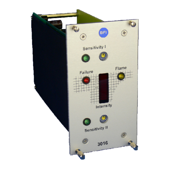
Failure Flame T> T< Intensity Sensitivity II 3016 LED display – sensitivity I active Rotary switch - setting – sensitivity I LED display - failure LED display – flame relay active LED bar graph - Intensity LED display – sensitivity II active... -
Page 24: Device Design
Technical data Device design The system slide-in module of the flame amplifier is based on a signal processor circuit with fail-safe self-monitoring system and has been approved for continous operation in keeping with European standard EN298 as well as TRD 411 - 414. -
Page 25: Block Diagram
Technical data Block diagram Signal processing a2/c2 Supply 24V DC Clock generator a4/c4 Supply 0V (GND) Monitor channel a6/c6 System clock µP Evaluation channel a8/c8 Flame signal Switch sensitivity 1 Sensetivity II “ON”, 24V DC/40mA Switch sensitivity 2 Failure Bargraph display a20/(c4) 24V PLC / (internal) Sensetivity switch... - Page 26 Technical data...
-
Page 27: Transport, Installation And Connection
Observe the legal stipulations and adjustment instructions of the plant operator ! Scope of delivery • Flame amplifier 3016 • Operating instructions BA 3016 EN • Backpanel with screw terminal (optional) • Pin connector (optional) • Connection cable (optional) • 19" rack (optional) •... -
Page 28: Packaging
Do not drop the device during transport and do not subject to heavy impacts. Weight - flame amplifier 0.5 kg Space requirement See following illustration, depth 188 mm. 70,78 (14TE - 0,34 ) Sensitivity I Failure Flame T> T< Intensity Sensitivity II 3016... -
Page 29: Installation
Transport, installation and connection Installation 4.6.1 19”-built-in housing (rack mount installation) 55 58 4.6.2 19”-built-on housing (wall mount installation) 4.6.3 Dimensions for 19”-built in/on housing 14 TE 28 TE 42 TE 56 TE 84 TE All dimen- for 1 slide-in for 2 slide-in for 3 slide-in for 4 slide-in... -
Page 30: Connection
Transport, installation and connection Connection 4.7.1 Electrical connection Danger to life caused by electrical current ! The safety instructions and local safety regulations have to be observed during connection ! For connection data, please refer to the chapter titled "Technical data" as well as to the following terminal dia- gram. -
Page 31: 4.7.2 Terminal Diagram 3016
Transport, installation and connection 4.7.2 Terminal diagram 3016 +24V T0.5A supply 24V DC/0,5Amax. pulse connection of flame scanner supply 0V ground (GND) sensitivity I 0V switchover sensitivity II 24V DC/40mA max. failure sensitivity II "ON" measurement channel 0/4-20mA Intensity 24V SPS or internal set to 24V with jumper X2 subsidiary circuit flame "OFF"... -
Page 32: 4.7.3 Terminal Diagram For Using Back Panel 3001
Transport, installation and connection 4.7.3 Terminal diagram for using back panel 3001 Back panel 3016 Function power supply input +24 VDC scanner 1: +24 VDC scanner 2: +24 VDC scanner 1: self-test pulse scanner 2: self-test pulse scanner 1: flame signal... -
Page 33: Storage
Transport, installation and connection Storage Do not unpack the packed flame amplifier and accesso- ries. The following conditions apply to storage: • Store in a dry place. Maximum relative humidity 60 %. Make sure that packages are not stored in the open. In addition, It has to be assured that the floor in the stor- age area will remain dry throughout the storage period. - Page 34 Transport, installation and connection...
-
Page 35: Description
Description Application In combination with a BFI flame scanner, the flame ampli- fier 3016 offers a fail-safe flame monitoring system. The fast switch-off time (adjustable between 200 and 650 ms) can be considered as the most excellent feature. More- over, a malfunctioning channel has also been integrated, indicating flame scanner;... -
Page 36: Sensetivity Adjustment
Description A self-test rate is generated. The pulses (or digits) sup- plied by the flame scanner are conditioned at first, to eliminate cable loss and interference. Subsequent to this, the signal path is split into two. An analogue monitoring channel ensures a safe switch-off in case of a failure of the parallel operating processor cir- cuit. - Page 37 Description The enclosed list features the connection between inten- sity and pulse rate. Sensetivity Flame-ON Flamme-OFF adjustment Table 5.4...
-
Page 38: Switch-Off Time
Description Switch-Off time The switch-off time is the time between flame failure and drop-out of the flame relay. This time is adjustable by means of a turn-switch (S 2) The switch is situated on the main PCB, i.e. the plug- in unit has to be removed from the rack for this purpose. -
Page 39: Option Unit
Description Option unit An additional jumper block with four DIP switches (S1.x) allows: 1. A manual selection of the sensitivity channel II 2. n.n. 3. The storage of a detected failure 4. The selection of the Intensity output signal 0/4 – 20mA 5.6.1 Choice of sensitivity level II The sensitivity level can be chosen by DIP switch S1.1. -
Page 40: Current Output
Description Bargraph Abbreviation Failure (from top) Flame detected, but to small signal Flame signal fault No flame scanner connected or no data Flame scanner -> cable damaged diagnostics T > Shutter period (to long) T < Shutter period (to short) Monitor- und Proces- sor channel unequal The second failure may also happen with a defect flame... -
Page 41: Wiring
Description Wiring The 24 V DC power supply is internally protected by a 500mA fuse which is soldered on the PCB. The dimen- sion of the fuse is of such a value that a flame scanner could be connected at the same line. A damage of the fuse is only expected by a defect of the system or by a wrong wiring. -
Page 42: Parallel Connection Of Flame Scanners
The pin con- nectors a4, a6, a8, a10 and a12 are used to connect a flame scanner. The pin connectors c4, c6, c8, 10 and c12 are used to connect the second flame scanner. flame amplifier backpanel flame scanner 3016 +24VDC +24VDC... -
Page 43: Operation Of The Flame Amplifier
Operation of the flame amplifier Operation of the flame amplifier All installation and connection work may be carried out by qualified and approved specialist staff only ! Prior to initial operation, all regulations and adjustment parameters set up by the operating company of the burner have to be observed ! For the operation of the flame amplifier, please observe the separate operating instructions of the flame scanner ! -
Page 44: Initial Operation Of The Flame Amplifier
Operation of the flame amplifier Initial operation of the flame amplifier The flame amplifier provides the flame scanner with oper- ating voltage and the self test pulse, and ensures the evaluation of the flame scanner signals. All safety-related functions are carried out by the self-checking flame ampli- fier. -
Page 45: Maintenance And Servicing
Maintenance and servicing Maintenance and servicing The flame amplifier 3016 requires no maintenance. For cleaning, use a moist cloth to wipe the front panel from the outside only. - Page 46 Maintenance and servicing...
-
Page 47: Failures
Failures Failures Problem: Display: Cause: Remedy: No flame - No analogue Flame ampli- Check power supply ON signal signal fier is not op- Check fuse F1 (T 0.5 after the erational LED “Flame” amps) burner has Replace flame ampli- been LED sensi- fier started... - Page 48 Failures...
-
Page 49: Order Data
Order data Order data Flame amplifier 3016 is available from BFI Automation GmbH under the following order data: Order-Nr.: Flame amplifier 3016 G 616 Table 9... - Page 50 Order data...
-
Page 51: Accessories
Accessories Accessories BFI Automation offers the following accessories: Type Order-No.: 19“-built-on housing, one- G 701 part, 14TE, IP 20 with back panel 3000F 19“-built-in housing one- G 701.1 part, 14TE, IP 20 with back panel 3000R 19“-built-in housing, one- G 701.2 part, 14TE, 32-pole female connector style „D“... - Page 52 Accessories 19“-built-on housing, six- G 706 parts, 84TE, IP 20 with back panel 3000F 19“-built-in housing, six- G 706.1 parts, 84TE, IP 20 with back panel 3000R 19“-built-in housing, six- G 706.2 parts, 84TE, 32-pole fe- male connector style „D“ 19“-built-in housing, six- G 706.3 parts, 84TE, Termi-Point,...
- Page 53 Accessories Rack 84TE, 3HE, with 6 x G 801.2 back panel 3000F back panel 3001F E 301.0 back panel 3001R E 301.1 Table 10 10-3...
- Page 54 Accessories 10-4...
- Page 55 Accessories 10-5...
- Page 56 Accessories You will find further information about BFI-Automation and our products under: Products catalog download under http://www.bfi-automation.de/download/bfi_pk_en_digi.pdf with QR-Code Image brochure download under http://www.bfi-automation.de/download/image_en.pdf with QR-Code © BFI Automation 2016 10-6...
Need help?
Do you have a question about the 3016 and is the answer not in the manual?
Questions and answers