Table of Contents
Advertisement
Advertisement
Table of Contents

Subscribe to Our Youtube Channel
Related Manuals for BFI Automation 3001D


Summary of Contents for BFI Automation 3001D
- Page 1 Original Operating Instructions Flame Amplifier Type: 3001D Document: BA 3001D EN REV.0 BFI Automation Dipl.-Ing. Kurt-Henry Mindermann GmbH Eggerscheidter Strasse 57 D-40883 Ratingen Germany Telephone +49 (2102) 9682-0 · Facsimile +49 (2102) 9682-42 http://www.bfi-automation.de...
-
Page 3: Table Of Contents
Content General aspects Introduction Warning notes Copyright protection Warranty Obligation of the operating company Liability disclaimer Declaration of conformity Address of the manufacturer Safety Intended use Requirements on persons Safety instructions Safety devices 2.4.1 Fundamental aspects 2.4.2 Safety devices on the flame amplifier Safety instructions in case of maintenance and troubleshooting 2.5.1 Fundamental aspects... - Page 4 Description Functional description 5.1.1 Measurement channel (M) 5.1.2 Monitor channel (RM) 5.1.3 Evaluation channel (RF) 5.1.4 Variable switch-ON threshold (hysteresis) 5.1.5 Fixed switch-OFF threshold 5.1.6 Pre-alarm warning 5.1.7 Safety switch-OFF times 5.1.8 Signal outputs 5.1.9 Impuls divider 5.1.10 Parallel connection of flame scanners Operation of the flame amplifier Connection of the flame amplifier Testing the flame amplifier...
-
Page 5: General Aspects
General aspects General aspects Introduction These operating instructions are a helpful guide for ensur- ing the successful and safe operation of the flame ampli- fier. They contain important information on how to operate the system safely, correctly and efficiently. Observing the operating instructions will help to prevent hazards, reduce costs of repair and downtimes and increase the reliability and life of the device. -
Page 6: Warning Notes
General aspects Warning notes The following warning notes are used in these operating instructions: This warning level indicates an imminent hazardous situa- tion. If the hazardous situation is not prevented, this will result in death or severe injury. Follow the instructions that accompany this warning to prevent the risk of death and severe personal injury. -
Page 7: Copyright Protection
These operating instructions have to be treated as confi- dential. They may only be used by authorised staff. Ac- cess by third parties may only be granted upon written agreement of BFI Automation. All documents are protected in keeping with the German copyright law. -
Page 8: Warranty
• non-performance of specified maintenance work It is recommended that the operator of the device con- cludes a service contract with BFI Automation. This guar- antees that the device is regularly checked by our service staff and ensures that any required wearing and spare... -
Page 9: Obligation Of The Operating Company
General aspects Obligation of the operating company The flame amplifier may cause hazards if it is operated inappropriately or in an improper condition. The operating company is under the obligation to operate the machine in proper state only. The operating company has to secure hazardous areas that exist between BFI devices and the customer's own equipment. -
Page 10: Liability Disclaimer
BFI Automation for consequential damages. BFI Automation is liable for possible errors or omissions with the exclusion of additional claims entered into in the framework of the warranty obligations conceded to in the contract. -
Page 11: Declaration Of Conformity
This declaration of conformity of the European Communi- ties is the result of an examination of the TD Department of BFI Automation in accordance with the European Standards. If the system will be changed without our ap- proval this declaration will become invalid. -
Page 12: Address Of The Manufacturer
General aspects Address of the manufacturer BFI Automation Dipl.-Ing. Kurt-Henry Mindermann GmbH Eggerscheidter Strasse 57 D-40883 Ratingen Germany Tel. +49 (2102) 9682-0 Fax. +49 (2102) 9682-42 E-mail: info@bfi-automation.de Internet: www.bfi-automation.de... -
Page 13: Safety
Safety Safety Intended use The flame amplifier shall be used exclusively to detect flames in combination with a suitable flame scanner. The flame scanner and flame amplifier together constitute a complete flame monitoring system for burners with a ran- dom capacity and random fuels in single and multiple burner systems. -
Page 14: Requirements On Persons
Safety Requirements on persons Work on/with the device may only be performed by per- sons authorized to do so based on their training and quali- fication. Furthermore, such persons have to have been commissioned by the operating company. Do not allow any persons who are being apprenticed, educated, instructed or on a general training programme to work on the device without the constant supervision of an experienced person. -
Page 15: Safety Instructions
Safety Safety instructions The following instructions on accident prevention have to be observed when operating the flame amplifier. Only operate the device if it is in a proper state ! • Do not remove or disable safety devices. • Check for externally noticeable damage and defects prior to using the device ! Immediately notify the ap- propriate authority/person of any changes that occur (including changes in operating performance). -
Page 16: Safety Devices
Safety Safety devices 2.4.1 Fundamental aspects Check the safety equipment and locking devices on the device for safe operational condition. Only operate the device if all safety devices are present and enabled. The operating company or operator of the flame amplifier is responsible for the proper operation of the device. -
Page 17: Safety Instructions In Case Of Maintenance And Troubleshooting
• Operating and auxiliary materials as well as exchanged parts have to be disposed of in a safe and eco-friendly way. • Spare parts supplied by BFI Automation or approved of by BFI Automation only may be used. -
Page 18: Electrical / Electronic Devices
Safety 2.5.2 Electrical / electronic devices Danger to life caused by electrical current! Contact with live wires or components presents a danger to life ! Prior to any work on the electrical equipment, disconnect the flame monitoring system from the power supply net- work ! In keeping with the electrical regulations, work on electri- cal / electronic parts / components may only be carried... -
Page 19: Testing In Keeping With The German Workplace Safety Ordinance (Betrsichv)
Safety 2.5.3 Testing in keeping with the German Work- place Safety Ordinance (BetrSichV) In case of the coupling or installation of devices from vari- ous manufacturers or suppliers, the operating company has to carry out a precise test, prior to start-up, in keeping with the German Workplace Safety Ordinance (BetrSichV) in force and the applicable electrical regulations. - Page 20 Safety...
-
Page 21: Technical Data
Technical data Technical data General characteristic features • Self-control to verify flawless function of the device in keep- ing with European standards EN 230, EN 298 and TRD 411 to 414. • Two externally selectable sensitivity and time levels • Fully electronic construction •... -
Page 22: Weight
Technical data connected load + 24 V DC, 500 mA current consumption approx. 300 mA (plus flame scanner) range of operating temperature -20 degrees to +60 degrees C (-4 degrees to +140 degrees F) applies for the safety circuit VDE 0110, class C, 250 V maximum switching voltage 250 V ohmic load... -
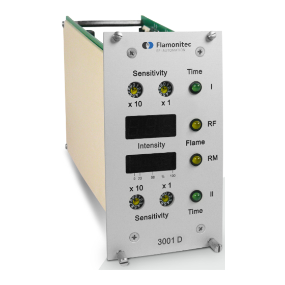
Page 23: Adjustment And Display Elements
Technical data Adjustment and display elements Sensitivity Time x 10 Flame Intensity 0 20 x 10 Sensitivity Time 3001 D 1 Rotary switch - setting – sensitivity I (x10 + x1) 2 Flame evaluation display 3 Bar-graph display - analogue output / LED pre-alarm 4 Rotary switch - setting - sensitivity II (x10 + x1) 5 LED display - time I / sensitivity I active 6 LED display - RF status evaluation channel... -
Page 24: Device Design
Technical data Device design The system slide-in module of the flame amplifier is based on a signal processor circuit with fail-safe self-monitoring system and has been approved for continous operation in keeping with European standards EN 240 and 298 as well as in conformity with TRD 411-414. -
Page 25: Block Diagram
Technical data Block diagram & & K101 & sensitivity 1 DIP switch S2 (RF2). sensitivity 2 DIP switch S3 (RF1). PWM pulse width modulation DIP switch S4 (RM2). self-test pulse DIP switch S5 (RM1). Relay switch-over switch-OFF time RF (1 - 6 s). measurement channel switch-OFF time RM (1 - 6 s). - Page 26 Technical data...
-
Page 27: Transport, Installation And Connection
! Observe the legal stipulations and adjustment instructions of the plant operator ! Scope of delivery • Flame amplifier 3001D • Operating instructions • Backpanel with screw terminal (optional) • Pin connector (optional) • Connection cable (optional) •... -
Page 28: Packaging
Transport, installation and connection Packaging The flame amplifier is shipped in different packagings. The most frequently used packaging materials are card- board and plastics (foils, foamed material). The packaging material also includes materials added to the packed goods as protection against moisture (e.g. bags with sili- cagel). -
Page 29: Installation
Transport, installation and connection Installation 4.6.1 19”-built-in housing (rack mount installation) 55 58 4.6.2 19”-built-on housing (wall mount installation) 4.6.3 Dimensions for 19”-built in/on housing 14 TE 28 TE 42 TE 56 TE 84 TE All dimen- for 1 slide-in for 2 slide-in for 3 slide-in for 4 slide-in... -
Page 30: Connection
Transport, installation and connection Connection 4.7.1 Electrical connection Danger to life caused by electrical current ! The safety instructions and local safety regulations have to be observed during connection ! For connection data, please refer to the chapter titled "Technical data" as well as to the following terminal dia- gram. -
Page 31: Terminal Diagram
Transport, installation and connection 4.7.2 Terminal diagram 3001D F101/F0.8A +24VDC +24VDC GND1 GND1 V110 +24VDC/100mA K1 v K2 +15VDC/10mA K101 +24VDC F102/T1A K101 GND1 Backpanel 3001D function Power supply input +24 VDC scanner 1 - Power supply +24 VDC scanner 2 - Power supply +24 VDC... -
Page 32: Storage
Transport, installation and connection Storage Do not unpack the packed flame amplifier and accesso- ries. The following conditions apply to storage: • Store in a dry place. Maximum relative humidity 60 %. Make sure that packages are not stored in the open. In addition, It has to be assured that the floor in the stor- age area will remain dry throughout the storage period. -
Page 33: Description
20 mA. In addi- tion, the flame amplifier generates all signals which are required for self-tests. The self-test and failsafe flame amplifier 3001D consists of two separate signal processing channels of different design. Internal and external disturbances of any kind lead to immediate actuation of the safety logic. -
Page 34: Measurement Channel (M)
Description 5.1.1 Measurement channel (M) The analogue measurement channel consists of an at- tenuation filter with signal limiter and downstream voltage- to-current converter. The converter supplies the internal analogue intensity display and the remote display instru- ment with 0 to 20 mA or 4 to 20 mA through output termi- nals. -
Page 35: Monitor Channel (Rm)
Description 5.1.2 Monitor channel (RM) The monitor channel processes the flame signal of the flame scanner. It comprises all periodic self-tests of the system required for continuous operation. In case of a failure of the flame monitoring system, the control logic responds immediately and the monitor channel RM switches-OFF. -
Page 36: Variable Switch-On Threshold (Hysteresis)
Description 5.1.4 Variable switch-ON threshold (hysteresis) The switch-ON threshold of the evaluation channel is variable and can be set by means of DIP switch S1. The adjustable range is between 25 and 75% of the analogue flame signal. The device has been factory set to 25%. A higher switch-ON threshold may sometimes be used to block out light from neighbour burners. -
Page 37: Safety Switch-Off Times
Description 5.1.7 Safety switch-OFF times The safety switch-OFF times of the operating process can be set by means of DIP switches S2 to S5 (cf. chapter 6). The following allocation applies: S2 - RF channel on time 2 S3 - RF channel on time 1 S4 - RM channel on time 2 S5 - RM channel on time 1 The switch-OFF times can be set to between 1 and 6... -
Page 38: Signal Outputs
Description 5.1.8 Signal outputs The potential-free relay contact for the "Flame on / off" message is internally protected by a fine wire fuse (T 1 amp). This prevents a fusing of contacts. When the device has been plugged-out, the fuse is accessible and can be replaced, if and when necessary. -
Page 39: Parallel Connection Of Flame Scanners
The pin connectors c4, c6, c8, 10 and c12 are used to connect the second flame scanner. flame amplifier backpanel flame scanner 3001D +24VDC GND1 +24VDC GND1... - Page 40 Description...
-
Page 41: Operation Of The Flame Amplifier
Operation of the flame amplifier Operation of the flame amplifier All installation and connection work may be carried out by qualified and approved specialist staff only ! Prior to initial operation, all regulations and adjustment parameters set up by the operating company of the burner have to be observed ! For the operation of the flame amplifier, please observe the separate operating instructions of the flame scanner ! -
Page 42: Initial Operation Of The Flame Amplifier
Operation of the flame amplifier Initial operation of the flame amplifier The flame amplifier provides the flame scanner with oper- ating voltage and the self test pulse, and ensures the evaluation of the flame scanner signals. All safety-related functions are carried out by the self-checking flame ampli- fier. -
Page 43: Operation Settings
Operation of the flame amplifier Operation settings Prior to the initial operation, check the setting of the switch-ON times and adjust, if and when necessary. DIP switches S2 to S5 are accessible on the upper side of the device. For this purpose pull the flame amplifier out of the 19"... - Page 44 Operation of the flame amplifier...
-
Page 45: Maintenance And Servicing
Maintenance and servicing Maintenance and servicing The flame amplifier requires no maintenance. For cleaning, use a moist cloth to wipe the front panel from the outside only. - Page 46 Maintenance and servicing...
-
Page 47: Failures
Failures Failures Problem: Display: Cause: Remedy: No flame - ON No analogue Flame amplifier Check power supply signal after the signal is not operational Check fuse F101 (F 0.8 amps) burner has LED RF OFF Replace flame amplifier been started LED RM OFF Check electrical connection LED time I /... - Page 48 Failures...
-
Page 49: Order Data
Order data Order data Flame amplifier 3001D is available from BFI Automation GmbH under the following order data: Flame amplifier 3001D Part-No.: G 601.D...
Need help?
Do you have a question about the 3001D and is the answer not in the manual?
Questions and answers