Advertisement
Quick Links
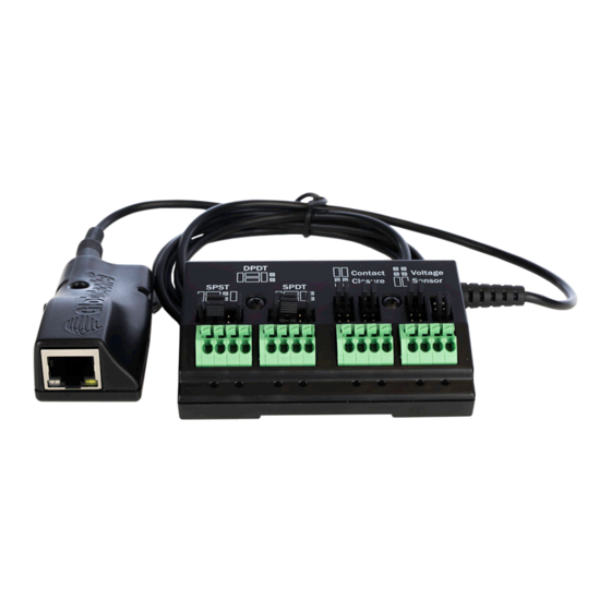
IP to Relay Command Converter for Velocity Control System
AT-VCC-RELAY-KIT
The Atlona AT-VCC-RELAY-KIT is an accessory for the Atlona Velocity™ Control System that
provides conversion between IP control commands and relay / sensor signals. This Velocity
Control Converter is very compact and can be placed anywhere a device requires control and
is not IP-capable. The VCC-RELAY-KIT is remotely powered through Power over Ethernet (PoE),
or locally from a USB power source. The primary unit installs onto any surface via a convenient
mounting dock. A simple "click" locks it into place for a secure, reliable installation. The control
port module supports DIN rail installation, and features four relay outputs plus four sensor inputs.
The inputs and outputs are both configurable for various operating modes.
Package Contents
1 x AT-VCC
1 x AT-VCC-RELAY
Operating Notes
•
The AT-VCC-RELAY-KIT is PoE, to power the unit, simply plug it into a PoE compatible
network switch. If the network switch is not PoE capable, a PoE injector
or USB can be used.
•
All devices (AT-VCC, Velocity, AT-VTP, switchers, etc) should be set to static IPs or the
DHCP IP address reserved for each individual device.
IMPORTANT: Velocity Gateway (AT-VGW-HW) must be set up before the AT-VCC-RELAY-
KIT is fully functional.
1
Installation Guide
AT-VCC-RELAY-KIT
(purchased separately)
Advertisement

Subscribe to Our Youtube Channel
Related Manuals for Atlona AT-VCC-RELAY-KIT

Summary of Contents for Atlona AT-VCC-RELAY-KIT
- Page 1 1 x AT-VCC-RELAY Operating Notes • The AT-VCC-RELAY-KIT is PoE, to power the unit, simply plug it into a PoE compatible network switch. If the network switch is not PoE capable, a PoE injector (purchased separately) or USB can be used.
-
Page 2: Panel Description
Installation Guide AT-VCC-RELAY-KIT Panel Description Ethernet Sensor Connect an Ethernet cable from this Connect sensor here, adjusting the port to the same network as the Velocity jumpers to the correct mode. Gateway. 3.5mm Connector Connect the 3.5mm connector to the Optional - Connect a mini USB to USB 3.5mm port of the VCC. - Page 3 Installation Guide AT-VCC-RELAY-KIT Single Pole, Double-Throw (SPDT) Place the jumpers as shown below, this can be done to a single connector or to both to create up to 3 independent relays. SPST SPDT SPDT SPDT Single Pole, Double-Throw is best used when two circuits are going to one common, such as: switching between two input circuits or selecting two power sources.
- Page 4 Connect the AT-VCC to a network switch (PoE is best if a PoE switch is not available, a power injector or mini USB to USB cable may be used). Download VHelp from the resource tab of https://atlona.com/product/at-vcc-relay-kit/. Unzip the file to the local PC Double-click the VHelp executable to open the program.
- Page 5 Select the room the VCC is located in. A new screen will take over the window and display the technology in the room. Select the + button located at the top right corner of the room. A new menu will open. Press the scan network button. All Atlona devices found will appear in the unassigned list.
- Page 6 Installation Guide AT-VCC-RELAY-KIT Select the Add button next to the VCC. A new pop up will appear. Select the VCC Relay/Sensor from the drop down menu. Press the ADD VCC TO ROOM button. A VCC tile will appear in the room.
- Page 7 Installation Guide AT-VCC-RELAY-KIT Security Security options have been provided with the VCCs, to set between web UI, API, and system lock. • Select Security from web UI menu. A new page will open. • To protect the web UI from being altered, a username and password can be set, once a username and password has been set, select the Save Changes button to enable login.
-
Page 8: Advanced Settings
Installation Guide AT-VCC-RELAY-KIT Advanced Settings If needed, the system can be rebooted or reset from the Advanced Settings page. Select it from the home page menu. • Reboot - Use this button to restart the unit. • Factory Reset - Use this to set everything back to default settings. This will reset the unit... -
Page 9: Firmware Update
Connect the AT-VCC to a network switch (PoE is best if a PoE switch is not available, a power injector or mini USB to USB cable may be used). Download VHelp from the resource tab of https://atlona.com/product/at-vcc-relay-kit/. Unzip the file to the local PC Double-click the VHelp executable to open the program. - Page 10 Installation Guide AT-VCC-RELAY-KIT Notes...
- Page 11 Installation Guide AT-VCC-RELAY-KIT Notes...
-
Page 12: Warranty
• © 2022 Atlona Inc. All rights reserved. “Atlona” and the Atlona logo are registered trademarks of Atlona Inc. All other brand names and trademarks or registered trademarks are the property of their respective owners. Pricing, specifications and availability subject to change without notice. Actual products, product images, and...
Need help?
Do you have a question about the AT-VCC-RELAY-KIT and is the answer not in the manual?
Questions and answers