Table of Contents
Advertisement
Quick Links
Use and Disclosure of Data
Information contained herein is classified as EAR99 under the
U.S. Export Administration Regulations.
Export, reexport or diversion contrary to U.S. law is prohibited.
INSTRUCTIONS FOR
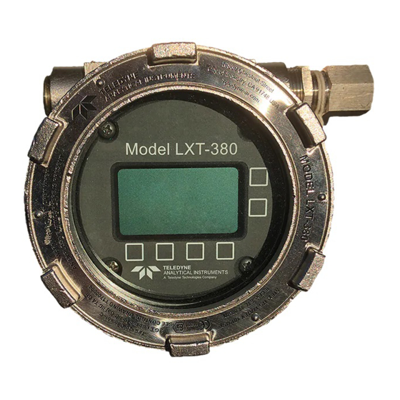
Model LXT-380
Universal Transmitter
P/N M LXT380
Date 12-19-17
DANGER
Toxic gases and or flammable liquids may be present in this instrument.
Personal protective equipment may be required when servicing this
instrument.
Hazardous voltages exist on certain components internally which may
persist for a time even after the power is turned off and disconnected.
Only authorized personnel should conduct maintenance and/or servicing.
Before conducting any maintenance or servicing, consult with authorized
supervisor/manager.
Teledyne Analytical Instruments
Advertisement
Table of Contents

Related Manuals for Teledyne Analytical Instruments LXT-380

Summary of Contents for Teledyne Analytical Instruments LXT-380
- Page 1 Use and Disclosure of Data Information contained herein is classified as EAR99 under the U.S. Export Administration Regulations. Export, reexport or diversion contrary to U.S. law is prohibited. INSTRUCTIONS FOR Model LXT-380 Universal Transmitter P/N M LXT380 Date 12-19-17 DANGER Toxic gases and or flammable liquids may be present in this instrument.
- Page 2 ...
- Page 3 EN 60079-0 : 2012+A11:2013; IEC 60079-0:2011 CONFORMITY IS DECLARED EN 60079-1: 2014; IEC 60079-1:2014-06 EN 60079-11: 2012; IEC60079-11:2011 EN 60079-18:2015; IEC 60079-18:2014 MANUFACTURER’S NAME TELEDYNE ANALYTICAL INSTRUMENTS MANUFACTURER’S ADDRESS : 16830 Chestnut Street City of Industry, CA 91748 U.S.A. TYPE OF EQUIPMENT...
- Page 4 ...
- Page 6 ...
- Page 7 LXT-380 Universal Transmitter Copyright © 2017 Teledyne Instruments/ Analytical Instruments All Rights Reserved. No part of this manual may be reproduced, transmitted, transcribed, stored in a retrieval system, or translated into any other language or computer language in whole or in part, in any form or by any means, whether it be electronic,...
- Page 8 LXT-380 Universal Transmitter Specific Model Information Instrument Serial Number: _______________________ Sample Gas 1: _______________ Zero Gas: _______________ Span Gas: _______________ Teledyne Analytical Instruments...
- Page 9 LXT-380 Universal Transmitter Safety Messages Your safety and the safety of others is very important. We have provided many important safety messages in this manual. Please read these messages carefully. A safety message alerts you to potential hazards that could hurt you or others.
- Page 10 LXT-380 Universal Transmitter CAUTION: THIS INSTRUMENT SHOULD ONLY BE USED FOR THE PURPOSE AND IN THE MANNER DESCRIBED IN THIS MANUAL. IF YOU USE THIS EQUIPMENT IN A MANNER OTHER THAN THAT FOR WHICH IT WAS INTENDED, UNPREDICTABLE BEHAVIOR COULD RESULT POSSIBLY ACCOMPANIED WITH HAZARDOUS CONSEQUENCES.
-
Page 11: Table Of Contents
LXT-380 Universal Transmitter Table of Contents List of Figures ................xi List of Tables ................xii 1.0 Introduction ................1 1.1 MODEL LXT-380 TRANSMITTER 1.2 BARRIER 9120019 1.3 STOPPING PLUG 9310062 1.4 SP3X SENSOR ... - Page 12 LXT-380 Universal Transmitter 2.2.2 WIRING, BARRIER 9120019 2.2.3 WIRING, SENSOR SP3X 2.2.4 WIRING, 4-20 MA OUTPUTS 2.2.5 WIRING, CONTACT RELAY OUTPUTS 2.2.6 WIRING, SERIAL OUTPUT MODBUS RTU 3.0 OPERATION ................17 3.1 MAGNETIC KEYS ...
- Page 13 LXT-380 Universal Transmitter 4.0.1 AUTO CALIBRATION DESCRIPTION 4.0.2 STANDARDIZE CALIBRATION DESCRIPTION 4.0.3 MANUAL CALIBRATION DESCRIPTION 4.1 pH CALIBRATION PROCEDURES 4.1.1 AUTO CAL USING pH 4.01, 7.00, 10.00 BUFFERS 4.1.2 AUTO CAL USING OTHER PH BUFFERS ...
- Page 14 LXT-380 Universal Transmitter 8.0 SP3X SENSORS ..............55 8.1 SP3X INSTALLATION 8.1.1 INSERTION 8.1.2 IMMERSION 8.1.3 FLOW THROUGH 8.1.4 VALVE RETRACTABLE 8.1.5 FLANGE FITTINGS 8.2 SP3X PART NUMBER CONFIGURATOR 8.3 SP3X SENSOR MAINTENANCE ...
- Page 15 LXT-380 Universal Transmitter Appendix ..................71 A. Auto Cal Buffer Tables B. LXT-380 Hart Menu C. MODBUS RTU REGISTER LISTING D. RESISTIVITY TEMPERATURE COMPENSATION E. Drawings F. Company Address Teledyne Analytical Instruments...
-
Page 16: List Of Figures
LXT-380 Universal Transmitter List of Figures Figure 2-1: Dimensions SS Housing ..........10 Figure 2-2: LXT-380 Transmitter Wiring Terminals ....... 11 Figure 2-3: B80 Barrier Wiring ............13 Figure 2-4: SP3X Sensor Connector Wiring ........14 ... -
Page 17: List Of Tables
LXT-380 Universal Transmitter List of Tables Table 1 Saturation Index ............... 44 Table 2 Altitude Correction ............45 Teledyne Analytical Instruments... - Page 18 Since the use of this instrument is beyond the control of Teledyne Analytical Instruments, referred as TAI, no responsibility by TAI, its affiliates, and agents for damage or injury from misuse or neglect of this equipment is implied or assumed.
- Page 19 LXT-380 Universal Transmitter Blank Page Teledyne Analytical Instruments...
-
Page 20: Introduction
Model LXT-380 transmitter communicates digitally with any Teledyne SP3X digital sensor, automatically configuring the transmitter’s menus and display screens to the measured parameter. The Model LXT-380 transmitter can be loop powered or 24 VDC powered. The standard configuration has a 4-20 mA output and a RS485 ®... -
Page 21: Barrier 9120019
Barrier part number 9120019 is intended for installation in hazardous locations with Zone 1, Ex d Gb classification. The barrier is installed into the LXT-380 flame-proof housing and performs two important functions. First, the barrier provides a flame-proof termination between the Model LXT-380 Transmitter Model SP3X Sensor. Second, the barrier provides intrinsically safe outputs to the SP3X Sensor by limiting available energy to the SP3X Sensor. -
Page 22: Stopping Plug 9310062
• Substitution of components is NOT PERMITTED and may impact intrinsic safety. • Ensure a minimum 5 full threads of engagement. • Connect and verify green wire to LXT-380 grounding lug. 1.3 STOPPING PLUG 9310062 IECEx: SIR 07.0082X ATEX: SIRA 07ATEX1240X... -
Page 23: Features
Introduction LXT-380 Universal Transmitter The Model SP3X Sensor is intrinsically safe and intended for installation in hazardous locations with Zone 0, Ex ia Ga classification. Energy available to the sensor is limited by the barrier to intrinsically safe levels. The maximum stored energy in the SP3X Sensor is below the level needed to generate spark ignition of the environment under any condition. -
Page 24: Specifications
LXT-380 Universal Transmitter Introduction 1.6 SPECIFICATIONS 1.6.1 INPUT SPECIFICATION Digital protocol, all Teledyne SP3X Sensors 1.6.2 INPUT RANGES -1.00 - 15.00 pH -1500 - +1500 mV pION 000.1 - 999.9, Auto Ranging: ppb ↔ ppm ↔ ppt (thousand) Dissolved Oxygen 000.1 - 999.9, Auto Ranging: ppb ↔ 20.00... -
Page 25: Contact Relays
Introduction LXT-380 Universal Transmitter 1.6.5 CONTACT RELAYS (Optional) Three (3) SPDT, 1 form C, 250 VAC, 10 Amp resistive maximum, relays, user configurable as Hi/Lo alarms with expiration timer, Periodic Timers or Fault alarms. 1.6.6 DISPLAY 128 x 64 pixels (2.0” x 1.1”) LCD, Black on Grey background on... -
Page 26: Model Codes
00 No Mounting Model LXT-380 The above example shows part# LXT380-11-112-00: a two channel LXT-380 transmitter for use with two SP3X sensors, 24 VAC powered with two 4-20 mA outputs and MODBUS RTU and no mounting bracket. Teledyne Analytical Instruments... -
Page 27: Approvals
Introduction LXT-380 Universal Transmitter 1.8 APPROVALS 1.8.1 ENCLOSURE Teledyne Analytical Instruments... -
Page 28: Installation
Do not mount in direct sunlight or areas of extreme heat. The IP65 LXT-380 is suitable for outdoor use but it is best to mount it with a protective cover or sunshield to prevent discoloring over the years. Teledyne Analytical Instruments... -
Page 29: Wiring
LXT-380 Universal Transmitter Figure 2-1: Dimensions SS Housing 2.2 WIRING The LXT-380 installation consists of a flame-proof transmitter with enclosure; an integral intrinsically-safe energy limiting barrier and flame-proof seal; and an Intrinsically-safe sensor. Substitution of parts or unauthorized repairs are prohibited and will invalidate certification. -
Page 30: Figure 2-2: Lxt-380 Transmitter Wiring Terminals
LXT-380 Universal Transmitter Installation Figure 2-2: LXT-380 Transmitter Wiring Terminals WARNING: RISK OF ELECTRICAL SHOCK DISCONNECT POWER BEFORE OPENING INSTRUMENT. WARNING ELECTRICAL INSTALLATION MUST BE IN ACCORDANCE WITH THE NATIONAL ELECTRICAL CODE (ANSI/NFPA-70), CANADIAN ELECTRICAL CODE AND/OR ANY OTHER APPLICABLE NATIONAL OR LOCAL CODES. -
Page 31: Wiring, Power
4-20 mA2 cable to terminals #4 (out) and #2 (return) for a two channel instrument. Feed the cables through the gland fitting on the left hand side of the LXT-380. Tighten the cable gland to provide a good seal to the cable. -
Page 32: Figure 2-3: B80 Barrier Wiring
LXT-380 Universal Transmitter Installation ground lug provided inside the LXT-380 housing. If the installation is a single channel unit remember to install the sealing plug (supplied) and tighten to 55nM (41ft-lbs) to maintain the flameproof integrity. Figure 2-3: B80 Barrier Wiring... -
Page 33: Wiring, Sensor Sp3X
Installation LXT-380 Universal Transmitter 2.2.3 WIRING, SENSOR SP3X Mount the SP3X sensor into the process as needed. Route the sensor cabling and attach the connector as follows (See Figure 2-4 SP3X Sensor Connector Wiring): Slide parts onto cable including Backshell, Clamping Cage, Gromet and Shielding Ring. -
Page 34: Wiring, 4-20 Ma Outputs
Model LXT-380-XX-0 X-XX. 24 VDC powered instruments: For instruments powered by 24VDC (Model LXT-380-XX-1X- XX), connect the 4-20 mA cable(s) to terminals #3 (out) for channel 1 and #2 (return) and to terminals #4 (out) for channel 2 and #2 (return). - Page 35 Attach the sensor wires as shown in Figure 2-2 or as described on the diagram inside the LXT-380 cover. Feed the sensor cable through the gland fitting on the left hand side of the LXT-380. Do not use the same gland fitting for the AC power or Alarm/Relays. See MODBUS command register in Appendix D.
-
Page 36: Operation
3.1 MAGNETIC KEYS The keys on the Model LXT-380 transmitter are magnetic Hall Effect switches. Use the magnetic end of the supplied instrument screw driver to actuate the switches. -
Page 37: Home/Exit Key
Operation LXT-380 Universal Transmitter 3.1.1 HOME/EXIT KEY The HOME key performs two functions, it selects which Home Screen is displayed and it returns the active screen to the HOME Menu Screen from anywhere inside the menu structure. Three Display screens are available:... -
Page 38: Selection Adjustment Keys
I j k l m n o p q r s t u v w x y z { | } → ← 3.2 MENU STRUCTURE There are 4 main function screens on the LXT-380 with numerous subfunctions and screens. Figure 3-1 is a screen map of the LXT-380 display. Teledyne Analytical Instruments... -
Page 39: Figure 3-1: Lxt-380 Screen Map
Operation LXT-380 Universal Transmitter Figure 3-1: LXT-380 Screen Map Teledyne Analytical Instruments... -
Page 40: Hold (Output Hold)
LXT-380 Universal Transmitter Operation Double tap any Selection/Adjustment key to enter the HOME Menu Screen. Five menu choices will appear, CAL, CONFIG, INFO, SIM and HOLD. Each of the Menus is detailed below. 3.2.1 HOLD (OUTPUT HOLD) Actuating the HOLD Key activates the HOLD function, HOLD is ON, displayed. -
Page 41: Config (Configuration Menu)
Operation LXT-380 Universal Transmitter ORP Calibration Solutions: Quinhydrone saturated: pH 4.01= +89 mV, pH 7.00= +266 mV. pION Calibration Solutions: 1.00, 10.00, 100.0 ppb, ppm, ppt (thousand). Dissolved Oxygen: Zero ppm (Sodium sulfite, Na2SO3 in water), Air saturated water, 8.25 ppm. - Page 42 LXT-380 Universal Transmitter Operation • GRAPH provides the choice of which Graph style is displayed on the Home screen. • LINE, Moving average, vertical scale set to 0- 100% of the 4-20 mA output and user defined time scale. •...
- Page 43 Operation LXT-380 Universal Transmitter • Optional 2 4-20 mA, same as above • RELAY • RLY1,2,3 Choose relay type: • Alarm, enter the Set point ON, Set Point OFF, Expiration time, Delay ON and Delay OFF times and the State, energize: changes state from de-energized to energized on alarm.
-
Page 44: Info (Information Menu)
LXT-380 Universal Transmitter Operation (simulate). Each level can be turned ON or OFF and can have a unique password. • MENU ON/OFF----- Locks Main Menu • CAL ON/OFF-----Locks CAL and CONFIG • CONFIG ON/OFF-----Locks CONFIG • SIM ON/OFF-----Locks SIM and CONFIG SENSOR enters the sensor configuration menu. -
Page 45: Sim (Simulation Menu)
Operation LXT-380 Universal Transmitter Transmitter Screen, details the Name, Power type, Serial #, Firmware version and the output configuration(s). Sensor Screen, details the Name, Part #, Serial # and three sets of Calibration data. 3.2.5 SIM (S IMULATION The Simulation menu allows the Input or Output signals to be simulated. -
Page 46: Fault Screens
® 3.2.7 SENTINEL SCREENS The SENTINEL feature allows the Model LXT-380 transmitter to provide Pre-pHault diagnostic information about the accuracy of a pH, ORP or pION measurement. The SENTINEL displays a filled triangular gauge that decreases proportionally to the degradation of the reference electrode. -
Page 47: Start Up Guide
60 mV apart (a full pH unit) then electrode service is required. 3.3 START UP GUIDE Install and wire the LXT-380 Transmitter as described in Sections 2.1 and 2.2 above. Connect the sensor to the transmitter as described in Section 2.2 above. -
Page 48: Configure 4-20 Ma Output Range
LXT-380 Universal Transmitter Operation calibration data and the range of measurement to the transmitter. The default configuration of the 4-20 mA output is the range of the sensor, 0- 14 pH for pH sensors, -1500 - +1500 for ORP or 0-XXXX ppm for a pION Sensor. -
Page 49: Configure Alarm Relays (Relays Optional)
Operation LXT-380 Universal Transmitter 3.3.3 CONFIGURE ALARM RELAYS (RELAYS OPTIONAL) • HOME Menu → Press CONFIG → XMTR → OUTPUT → RELAYS→RLY1 • Choose the ALARM, TIMER, FAULT or DISABLE mode for Relay 1. • ALARM Displays: • SET POINT ON: The Process Variable Value that activates the relay. -
Page 50: Exit Menus And Return To Main Display
LXT-380 Universal Transmitter Operation • DISABLE turns off the relay and removes it’s icon from the HOME screen. Setting up an Alarm Relay • Choose ALARM • Press CHANGE to enter new values • Choose ON Set Point, Press OK. -
Page 51: Sensor Start Up
Operation LXT-380 Universal Transmitter • “Save Changes?” press YES. • Choose Display Mode, DATA, mV or GRAF by pressing selection Key. The selection key displays which screen will be displayed next. • The type of graphical display used, Line, Bar or Gauge is selected in CONFIG →... -
Page 52: Tag Transmitter Name
LXT-380 Universal Transmitter Operation • LINE, The Line graph is a moving average of the process variable with the 4-20 mA range as the maximum/minimum values and a choice of time scales. The Time scale is the amount of time displayed across the full screen. -
Page 53: Sensor Name
Operation LXT-380 Universal Transmitter Location: CONFIG → XMTR → LCD → LABELS → TAG 3.4.4 SENSOR NAME Two 16 character lines are available for naming the Sensor, Upper and Lower case characters, Numbers and Punctuation are available. The information entered will be displayed in the INFO screen. Entry is accomplished by scrolling through the alphanumeric list with the ▲... - Page 54 LXT-380 Universal Transmitter Operation • MENU ON/OFF: Locks Main Menu • CAL ON/OFF : Locks CAL and CONFIG • CONFIG ON/OFF: Locks CONFIG • SIM ON/OFF: Locks SIM and CONFIG In the case of a Lost or Forgotten password enter MSTR to access the screen.
- Page 55 Operation LXT-380 Universal Transmitter Blank Page Teledyne Analytical Instruments...
-
Page 56: Auto Calibration Description
LXT-380 Universal Transmitter Calibration 4.0 CALIBRATION The Model LXT-380 transmitter provides three methods of calibration: Auto Calibration Standardize Calibration Manual Calibration 4.0.1 AUTO CALIBRATION DESCRIPTION Auto calibration is the primary calibration method for all measurements. AUTO calibration automatically recognizes the calibration solution the sensor is in and proposes the actual temperature compensated value for acceptance. -
Page 57: Standardize Calibration Description
Calibration LXT-380 Universal Transmitter 4.0.2 STANDARDIZE CALIBRATION DESCRIPTION A Standardize Calibration is a single point calibration where the transmitter’s reading is adjusted to agree with a solution of known value, either a calibration standard, a grab sample or laboratory determined value. In many cases the constituents and the pressure and temperature of the process solution are very different from the calibration solution. -
Page 58: Ph Calibration Procedures
LXT-380 Universal Transmitter Calibration sensor. Press MANUAL and enter the pH value, 7.00 pH, press mV and enter the corresponding mV value, 6.8 mV, press OK, Accept Offset?, press YES, enter slope 58.2 mV/pH, press OK, Accept Slope?, Press YES. -
Page 59: Auto Cal Using Other Ph Buffers
Calibration LXT-380 Universal Transmitter 4.1.2 AUTO CAL USING OTHER PH BUFFERS 4.1.3 STANDARDIZE Leave the sensor in the process solution, take a grab sample from the process and determine the pH or place sensor in a calibration standard solution. Teledyne Analytical Instruments... -
Page 60: Orp Calibration Procedures
LXT-380 Universal Transmitter Calibration 4.2 ORP CALIBRATION PROCEDURES AUTO Calibration recognizes Quinhydrone solutions (mVa), pH 7.00 quinhydrone solution (90 mV) and pH 4.01 quinhydrone solution (267 mV) for automatic ORP calibrations. Any calibration solutions can be used but the ORP value will have to be entered manually. Follow the steps below to accomplish an ORP calibration. -
Page 61: Pion Calibration Procedures
Calibration LXT-380 Universal Transmitter 4.3 PION CALIBRATION PROCEDURES AUTO Calibration recognizes 1, 10 or 100 ppm/ppb calibration solutions. Any calibration solutions can be used but the ppm value will have to be entered manually. Follow the steps below to accomplish a pION calibration. -
Page 62: Standardize
LXT-380 Universal Transmitter Calibration 4.3.3 STANDARDIZE Leave the sensor in the process solution, take a grab sample from the process and determine the Ion concentration. 4.4 SP3X DISSOLVED OXYGEN CALIBRATION PROCEDURES The dissolved oxygen AUTO Cal acknowledges zero ppm, mg/l, % SAT for CAL 1 and the temperature compensated value for atmospheric oxygen, 8.25 ppm, mg/l at 25°C or 100 % SAT for CAL 2. - Page 63 K = 0.960, Air Pressure 1.014 bar: C = 9.08 x 0.960 x 1.014 = 8.84 mg/L The LXT-380 transmitter uses the temperature compensated Saturation Index for AUTO Cal, however the user can enter the altitude and pressure compensated value of 8.84 ppm as the calibration value when prompted to “Accept Value?”...
-
Page 64: Conductivity Sensors
LXT-380 Universal Transmitter Calibration Table 2 Altitude Correction 4.5 CONDUCTIVITY SENSORS AUTO Calibration recognizes air for zero point (Cal 1) and 50μS, 100μS, 500μS, 1mS, 5mS, 10mS, 50mS and 100mS solutions for the span (Cal 2). Any calibration solutions can be used but the conductivity value will have to be entered manually. -
Page 65: Standardize
4.6 TDS CONDUCTIVITY SENSORS The Total Dissolved Solids measurement (TDS) on the Model LXT-380 transmitter is made with an SP3X conductivity sensor and a correlation factor. (Conductivity in μS x correlation factor = ppm). Conductivity is a measurement of a solution’s electrolytic conductivity, 1/ohms. -
Page 66: Standardize
LXT-380 Universal Transmitter Calibration around 6000 μS (correlation factor 0.1667). All three solutions have a TDS of 1000 ppm but the conductivities are 1400 μS, 2000 μS and 6000 μS. A TDS measurement is only valid for a solution with the same chemical make up as the solution used for calibration. -
Page 67: Auto Cal Using Air And Meg-Ohm Process Water
Calibration LXT-380 Universal Transmitter 4.7.1 AUTO CAL USING AIR AND MEG-OHM PROCESS WATER 4.7.2 STANDARDIZE With the sensor in the process solution, take a grab sample from the process and determine the conductivity using a qualified laboratory conductivity meter. Teledyne Analytical Instruments... -
Page 68: Maintenance
No periodic maintenance is required for the Teledyne Model LXT- 380 Transmitter. Do not open the LXT-380 enclosure in a hazardous environment without ensuring that NO hazardous gases, vapor or dust is present. Remove power prior to opening cover and/or performing any service, repair or cleaning. - Page 69 Maintenance LXT-380 Universal Transmitter Blank Page Teledyne Analytical Instruments...
-
Page 70: Troubleshooting
LXT-380 Universal Transmitter Troubleshooting 6.0 TROUBLESHOOTING Teledyne Analytical Instruments... - Page 71 Troubleshooting LXT-380 Universal Transmitter Blank Page Teledyne Analytical Instruments...
-
Page 72: Parts And Accessories
LXT-380 Universal Transmitter Parts and Accessories 7.0 PARTS AND ACCESSORIES 7.1 REPLACEMENT PARTS Teledyne Analytical Instruments... - Page 73 Parts and Accessories LXT-380 Universal Transmitter Blank Page Teledyne Analytical Instruments...
-
Page 74: Sp3X Sensors
Connect an SP3X pH sensor to a Model LXT-380 Transmitter and the Transmitter configures itself into a calibrated pH transmitter. -
Page 75: Immersion
SP3X Sensors LXT-380 Universal Transmitter sensor in place. The torque specification for the gland fitting is 20-ft/lbs. Over-tightening of the nut may swage the nylon or Teflon ferrules to the housing crushing the internal sensor components. 8.1.2 IMMERSION The ¾” MNPT compression fitting is reversed and threaded into an extension/immersion pipe so the compression gland is facing the measurement end of the sensor. - Page 76 LXT-380 Universal Transmitter SP3X Sensors tank wall. The ball valve system allows the sensor to be removed from service without shutting down the line or emptying the tank. Teledyne recommends the valve-retraction mounting for ease of maintenance or in applications where the process line cannot be shut down and the pressure does not exceed 100 psig.
-
Page 77: Flange Fittings
SP3X Sensors LXT-380 Universal Transmitter 8.1.5 FLANGE FITTINGS Flange mountings can be accomplished with the insertion and valve-retraction configurations using the desired flange and by mounting the gland fitting or valve-retraction assembly to the flange. 8.2 SP3X PART NUMBER CONFIGURATOR... - Page 78 LXT-380 Universal Transmitter SP3X Sensors Teledyne Analytical Instruments...
-
Page 79: Sp3X Sensor Maintenance
SP3X Sensors LXT-380 Universal Transmitter 8.3 SP3X SENSOR MAINTENANCE All electrochemical sensors require periodic cleaning and/or replacement. The life of an electrode is dependent on the process conditions it is exposed to, a pH electrode may last a year or longer in potable water and only a few weeks in a hot caustic bath. -
Page 80: Electrode Cartridge Installation
LXT-380 Universal Transmitter SP3X Sensors removing hard water scales and metallic deposits or spray washing for flocculants and biofilms. 8.3.1 ELECTRODE CARTRIDGE INSTALLATION Unless ordered separately, electrode cartridges are generally shipped installed in a sensor. Sensors ordered without an electrode are shipped with a shipping plug to keep contamination from getting inside the sensor during shipment or storage. -
Page 81: Electrode Cleaning
SP3X Sensors LXT-380 Universal Transmitter 8.3.3 ELECTRODE CLEANING An important aspect of sensor maintenance is the service of the electrode cartridge. After being in operation, an electrode may begin to exhibit slow response or non-reproducible measurements. This may be due to coating of the measurement electrode or clogging of the reference junction. -
Page 82: Pion Electrode Cartridge Cleaning
LXT-380 Universal Transmitter SP3X Sensors 8.3.6 PION ELECTRODE CARTRIDGE CLEANING Ion selective electrodes require periodic service. Weekly checks should be performed to assure the accuracy of the measurement. The ion selective crystal that senses the ion concentration can become sluggish in response due to coating or reactions with the process solution. -
Page 83: Dissolved Oxygen Cartridges
SP3X Sensors LXT-380 Universal Transmitter Fluoride Electrodes a. Moisten the end of the Q-tip with water and dip it in the alumina polishing powder to pick up a small amount of the powder. b. Rub the polishing powder onto the fluoride crystal in a circular motion and moisten the tip if necessary to produce a liquid consistency more than a paste. -
Page 84: Conductivity And Resistivity Sensors
LXT-380 Universal Transmitter SP3X Sensors 8.3.8 C ONDUCTIVITY AND ESISTIVITY SENSORS Cleaning agents should be specific to the type of coating, detergents or alcohols for removing greases and oils, acids for removing hard water scales and metallic deposits or spray washing with water and a soft brush for flocculants and biofilms. -
Page 85: Ph Electrodes
SP3X Sensors LXT-380 Universal Transmitter -75SF: ¾” 316 SS gland fitting with stainless steel ferrule. -75TFE: ¾” Teflon™ gland fitting with Teflon™ ferrule. -100: 1” Teflon™ glands fitting for PVDF housing only. -VSS: 1” 316 SS valve retraction assembly. -VKY: 1” PVDF valve retraction assembly. -
Page 86: Dissolved Oxygen
LXT-380 Universal Transmitter SP3X Sensors Measurement Range: -1500 mV - +1500 mV Temperature Range: -10° - 80°C Pressure Range: 150 psig 8.4.3 DISSOLVED OXYGEN Part#: 2005622 2 mil Teflon membrane Galvanic cell: Silver/Lead Construction: PEEK body, Measurement Range: 0-20 ppm Temperature Range: -10°... -
Page 87: Chloride Electrode
SP3X Sensors LXT-380 Universal Transmitter Construction: Radel (PES) body, Reference Electrode: double porous Teflon junction Measurement range: 0.1 - 40,000 ppm pH Range: 2.5 - 10 pH Temperature Range: 0°-40°C Pressure Range: 50 psig 8.4.7 CHLORIDE ELECTRODE Part #: 2005008 (2005308 SENTINEL) -
Page 88: Fluoride Electrode
LXT-380 Universal Transmitter SP3X Sensors 8.4.10 FLUORIDE ELECTRODE Part #: 2005163 (2005363 SENTINEL) ISE sensor: solid state LaF crystal Construction: PEEK body, Reference Electrode: double porous Teflon junction Measurement range: 0.02 - 2,000 ppm pH Range: 5-8 pH Temperature Range: 0°- 80°C Pressure Range: 50 psig 8.4.11 POTASSIUM ELECTRODE... -
Page 89: Sulfide Electrode
SP3X Sensors LXT-380 Universal Transmitter Temperature Range: 0°-80°C Pressure Range: 150 psig 8.4.14 SULFIDE ELECTRODE Part #: 2005122 (2005322 SENTINEL) ISE sensor: solid state AgS membrane Construction: PEEK body, Reference Electrode: double porous Teflon junction Measurement range: 0.01 - 32,000 ppm pH Range: 11-14 pH Temperature Range: 0°-80°C... -
Page 90: Appendix
LXT-380 Universal Transmitter Appendix Appendix A. Auto Cal Buffer Tables Teledyne Analytical Instruments... -
Page 91: Hart Menu
Appendix LXT-380 Universal Transmitter B. LXT-380 Hart Menu Teledyne Analytical Instruments... - Page 92 LXT-380 Universal Transmitter Appendix Teledyne Analytical Instruments...
-
Page 93: Modbus Rtu Register Listing
Appendix LXT-380 Universal Transmitter C. MODBUS RTU REGISTER LISTING 03 (0X03) READ HOLDING REGISTERS This function code is used to read the contents of a contiguous block of holding registers in a remote device. The Request Protocol Data Unit specifies the starting register address and the number of registers. - Page 94 LXT-380 Universal Transmitter Appendix 06 (0X06) WRITE SINGLE REGISTER This function code is used to write a single holding register in a remote device. The Request Protocol Data Unit specifies the address of the register to be written. Registers are addressed starting at zero.
- Page 95 Appendix LXT-380 Universal Transmitter REGISTERS Per the Modbus Application Protocol Specification (V1.1b) Teledyne Analytical Instruments...
- Page 96 LXT-380 Universal Transmitter Appendix Teledyne Analytical Instruments...
- Page 97 Appendix LXT-380 Universal Transmitter Teledyne Analytical Instruments...
- Page 98 LXT-380 Universal Transmitter Appendix Fault Status WARNING STATUS Teledyne Analytical Instruments...
- Page 99 Appendix LXT-380 Universal Transmitter Sensor Type Teledyne Analytical Instruments...
-
Page 100: Resistivity Temperature Compensation
°C for 18.2 MΩ water. For the range of 20°- 40°C the mean value is -5% per °C, this is the default value set in the Model LXT-380. The temperature coefficient of 10 MΩ water drops to a mean value of -2.6%. -
Page 101: Drawings
Appendix LXT-380 Universal Transmitter E. Drawings Teledyne Analytical Instruments... - Page 102 LXT-380 Universal Transmitter Appendix Teledyne Analytical Instruments...
- Page 103 Appendix LXT-380 Universal Transmitter Teledyne Analytical Instruments...
-
Page 104: Company Address
LXT-380 Universal Transmitter Appendix F. Company Address TELEDYNE ELECTRONIC TECHNOLOGIES Analytical Instruments 16830 Chestnut Street City of Industry, CA 91748 Telephone: (626) 934-1500 Fax: (626) 961-2538 Web: www.teledyne-ai.com or your local representative email: ask_tai@teledyne.com IMPORTANT: Orders for replacement parts should include the model number, serial number, and range of the analyzer for which the parts are intended.
Need help?
Do you have a question about the LXT-380 and is the answer not in the manual?
Questions and answers