Table of Contents
Advertisement
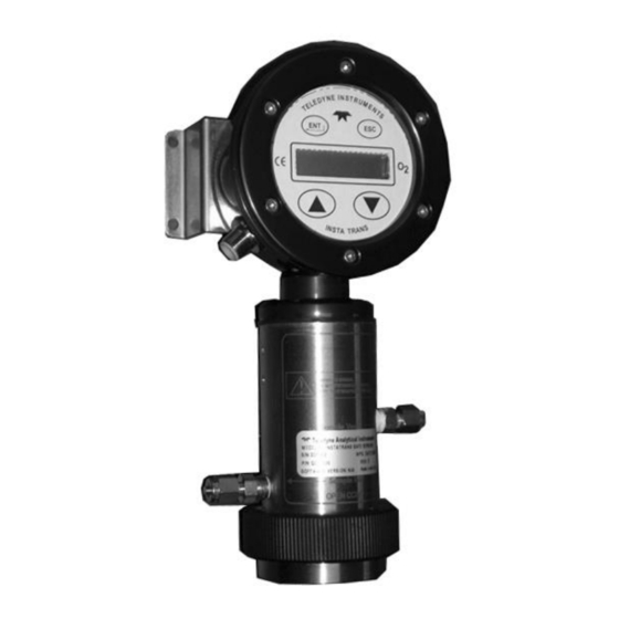
OPERATING INSTRUCTIONS FOR
INSTA TRANS-XD
Trace and Percent Oxygen Digital
Transmitter
P/N M82620
7-19-18
DANGER
Toxic gases and or flammable liquids may be present in this monitoring system.
Personal protective equipment may be required when servicing this instrument.
Only authorized personnel should conduct maintenance and/or servicing.
Before conducting any maintenance or servicing, consult with authorized
supervisor/manager.
Teledyne Analytical Instruments
i
Advertisement
Table of Contents

Related Manuals for Teledyne Analytical Instruments INSTA TRANS-XD

Summary of Contents for Teledyne Analytical Instruments INSTA TRANS-XD
- Page 1 OPERATING INSTRUCTIONS FOR INSTA TRANS-XD Trace and Percent Oxygen Digital Transmitter P/N M82620 7-19-18 DANGER Toxic gases and or flammable liquids may be present in this monitoring system. Personal protective equipment may be required when servicing this instrument. Only authorized personnel should conduct maintenance and/or servicing.
- Page 2 Teledyne Analytical Instruments, the manufacturer of this instrument, cannot accept responsibility for conditions beyond its knowledge and control. No statement expressed or implied by this document or any information disseminated by the manufacturer or its agents, is to be construed as a warranty of adequate safety control under the user’s process...
-
Page 3: Specific Model Information
Commonly available options are listed below, with check boxes. Any that are incorporated in the instrument for which this manual is supplied are indicated by a check mark in the box. Instrument Serial Number : _______________________ Cell Class: Insta-Trace Other Insta Trans-XD Transmitter Model: Teledyne Analytical Instruments... -
Page 4: Safety Messages
Insta Trans-XD Safety Messages Your safety and the safety of others are very important. We have provided many important safety messages in this manual. Please read these messages carefully. A safety message alerts you to potential hazards that could hurt you or others. - Page 5 Manuals do get lost. Additional manuals can be obtained from Teledyne at the address given in the Appendix. Some of our manuals are available in electronic form via the internet. Please visit our website at: www.teledyne-ai.com. Teledyne Analytical Instruments...
-
Page 6: Safety Information
Insta Trans-XD Safety Information WARNING: Substitution of components may impair intrinsic safety. WARNING: To prevent ignition of flammable or combustible atmospheres, read, understand and adhere to the manufacturer’s live maintenance procedures. WARNING: Potential electrostatic charging hazard. The enclosure contains plastic. To prevent the risk of electrostatic sparking the plastic surface should be cleaned only with a damp cloth. - Page 7 Since the use of this instrument is beyond the control of Teledyne, no responsibility by Teledyne, its affiliates, and agents for damage or injury from misuse or neglect of this equipment is implied or assumed. Teledyne Analytical Instruments...
-
Page 8: Certification/Approvals And Special Instructions
Insta Trans-XD Certification/Approvals and Special Instructions Factory Mutual (FM) TAI Model Insta Trans-XD IS Ex ia CL I, Div 1, Gp ABCD T4 @ Ta= 0 C to 50 TAI Model Insta Trans-XD Nonincendive for CL I, Div 2, Gp ABCD T4 @ Ta= 0 oC to 50 oC... -
Page 9: Atex Certification And Special Conditions For Safe Use
The electrical connections are not isolated from ground. This must be taken into account during installation and use. Teledyne Analytical Instruments... -
Page 11: Table Of Contents
2.2 Oxygen Sensor 2.2.1 Principles of Operation 2.2.2 Anatomy of a Micro-fuel Cell 2.2.3 Electrochemical Reactions 2.2.4 The Effect of Pressure 2.2.5 Calibration Characteristics 2.3 Sample System 2.4 Electronics and Signal Processing Installation ................... 13 3.1 Unpacking the Transmitter Teledyne Analytical Instruments... - Page 12 Insta Trans-XD 3.2 Mounting the Transmitter 3.3 Gas Connections 3.4 Electrical Connections 3.5 Installing the Oxygen Sensor 3.6 Powering UP and Testing the System Operation ..................19 4.1 Introduction 4.2 The Range and Calibration Functions 4.3 Range Setting 4.4 Calibration 4.4.1 Span Calibration...
-
Page 13: List Of Figures
Figure 2-3: Characteristic Input/output Curve for a Micro-fuel Cell ..9 Figure 2-4: Gas and Power/Signal Connections to the Transmitter10 Figure 2-5: Insta Trans-XD Internal Electronics ......11 Figure 2-6: Electronics Block Diagram .......... 12 Figure 3-1: Insta Trans-XD Connections and Mounting Dimensions .............. - Page 14 Insta Trans-XD [This page is intentionally blank] Teledyne Analytical Instruments...
-
Page 15: Introduction
The Teledyne Analytical Instruments Insta Trans-XD Oxygen Digital Transmitter is a versatile instrument for measuring the oxygen content in a gas sample. This manual covers the Insta Trans-XD Oxygen Digital Transmitter for both the ATEX and FM certified instruments. These units are rated Intrinsically Safe (IS) when installed per the... -
Page 16: Operator Interface
True 2-wire 4-20 mA powered loop interface. 1.4 Operator Interface The standard Insta Trans-XD is housed in a rugged metal case with all switches and the display accessible from the outside. Figure 1-1 illustrates the Insta Trans-XD display and switches. -
Page 17: Figure 1-1: Insta Trans-Xd User Interface
(user defined) R (Range setting mode) display blinking P (Percent value) Calibration Span S (display blinking) 4-20 mA Adjust 4.00 (low end) L (display blinking) 20.0 (high end) H (display blinking) Figure 1-1: Insta Trans-XD User Interface Teledyne Analytical Instruments... - Page 18 Introduction Insta Trans-XD [This page is intentionally blank] Teledyne Analytical Instruments...
-
Page 19: Operational Theory
2.2 Oxygen Sensor 2.2.1 Principles of Operation The oxygen sensor used in the Insta Trans-XD series is a micro- fuel cell designed and manufactured by Teledyne Analytical Instruments. It is a sealed plastic disposable electrochemical transducer. -
Page 20: Anatomy Of A Micro-Fuel Cell
Operational Theory Insta Trans-XD 2.2.2 Anatomy of a Micro-fuel Cell The Micro-fuel Cell is a cylinder only 1¼ inch in diameter with a length dependent on the particular cell. It is made of an extremely inert plastic, which can be placed confidently in practically any environment or sample stream. -
Page 21: Electrochemical Reactions
When the oxygen is reduced at the cathode, lead is simultaneously oxidized at the anode by the following HALF REACTION: O + 2e – – → Pb Pb + 2OH (anode) Teledyne Analytical Instruments... -
Page 22: The Effect Of Pressure
Operational Theory Insta Trans-XD (Two electrons are transferred for each atom of lead that is oxidized. Therefore it takes two of the above anode reactions to balance one cathode reaction and transfer four electrons.) The electrons released at the surface of the anode flow to the cathode surface when an external electrical path is provided. -
Page 23: Figure 2-3: Characteristic Input/Output Curve For A Micro-Fuel Cell
Figure 2-3. Measuring circuits do not have to compensate for nonlinearities. In addition, since there is zero output in the absence oxygen, the characteristic curve has close to an absolute zero (within ± 0.5 ppm oxygen). Figure 2-3: Characteristic Input/output Curve for a Micro-fuel Cell Teledyne Analytical Instruments... -
Page 24: Sample System
Depending on the mode of operation either sample or calibration gas is delivered. The Insta Trans-XD is designed and fabricated to ensure that the oxygen concentration of the gas is not altered as it travels through the internal piping. The sample encounters almost no dead space. This minimizes residual gas pockets that can interfere with trace analysis. -
Page 25: Electronics And Signal Processing
Oxygen Transmitter Operational Theory 2.4 Electronics and Signal Processing The Insta Trans-XD Oxygen Transmitter uses standard electronic circuitry. Power is supplied via the 4-20 mA current loop. The processing electronics are located inside the transmitter housing. The single PC board shown in Figure 2-5 is accessible after removing the front cover of the housing. -
Page 26: Figure 2-6: Electronics Block Diagram
Range selection and calibration information are entered from the keypad and processed by the microcontroller. All power needed to run the Insta Trans-XD transmitter is derived from the signal current loop. Range and calibration settings are maintained indefinitely when the signal current loop is disconnected. -
Page 27: Installation
Immediately report any damage to the shipping agent. 3.2 Mounting the Transmitter The Insta Trans-XD transmitter is provided with a wall mount bracket. Refer to Figure 3-1 and the Outline Drawing in the Appendix for mounting information and dimensions. The display and operator control switches are located on the top of the transmitter. -
Page 28: Figure 3-1: Insta Trans-Xd Connections And Mounting Dimensions
(This may require an additional 1/8 turn beyond finger-tight.) 2. Hold the fitting body steady with a backup wrench, and with another wrench rotate the nut another 1-1/4 turns. Figure 3-1: Insta Trans-XD Connections and Mounting Dimensions SAMPLE IN: Gas connections are made at the GAS GAS OUT connections. -
Page 29: Electrical Connections
(3/8") to the left side mounting bolt. The signal and power are supplied by a single 4-pin electrical connector on the left side of the analyzer. The Insta Trans-XD is supplied with a twenty-four inch cable which mates with the power/signal connector. -
Page 30: Installing The Oxygen Sensor
(9.3V + (5.1 + 250) ohms x 20ma). For Intrinsically Safe (IS) installation, special considerations are required. The Insta Trans-XD analyzer has been designed to be Intrinsically Safe when used with a properly selected and installed safety barrier. This design utilizes redundant safety features to prevent the Insta Trans-XD from becoming an ignition source in the event of a circuit failure. -
Page 31: Powering Up And Testing The System
Note: The transmitter can display a 99.9% over range condition, so select a range where the left-most digit is blank. 3. The unit will time out if another button is not pressed after a few seconds and return to Run mode. Teledyne Analytical Instruments... - Page 32 Installation Insta Trans-XD [This page is intentionally blank] Teledyne Analytical Instruments...
-
Page 33: Operation
IN THE EVENT OF LOSS OF FLOW THROUGH THE TRANSMITTER, IF THE VENT IS VENTED TO A LOCATION OF HIGH OXYGEN CONTENT, OXYGEN WILL BACK DIFFUSE THROUGH THE VENT LINE AND IN MOST CASES QUICKLY SATURATE THE CELL WITH OXYGEN. THIS MAY THEN REQUIRE A Teledyne Analytical Instruments... -
Page 34: Range Setting
2. Install a shut off valve on the vent port of the transmitter or somewhere within the users sample system. 4.3 Range Setting The Insta Trans-XD Transmitter can be set to any range from 0-10 ppm to 0-25 percent. The 0-10 ppm range is limited to instruments with trace sensors installed. -
Page 35: Span Calibration
(See Section 4.3), the 4-20 mA signal output will need to be calibrated. This is accomplished by attaching a DVM in current mode (mA) in series with the power input cable. When the Insta Trans-XD is placed in 4-20 mA Calibration mode, the output will display on the... -
Page 36: No Sensor Installed Detection Feature
2. Power OFF the Insta Trans-XD. 3. While pressing and holding the escape (ESC) key, power the unit back ON. This will place the Insta Trans-XD in 4-20 mA Calibration mode and the display will blink while showing the character “L” at the rightmost position of the display referring to the low end of the 4-20 range i.e. -
Page 37: Figure 4-1: No Sensor Display Warning
To disable the feature, press and hold the UP key button for 10 seconds. The display will show a bottom LCD segment bar flash on the rightmost side of the display, for example “00.0_” and then “00.0 ”. See Figure 4-2. Teledyne Analytical Instruments... -
Page 38: Cold Boot
To perform a cold boot: 1. Power OFF the Insta Trans-XD 2. While simultaneously pressing and holding the ENT and UP keys, power the system back ON. The Insta Trans-XD will proceed through the normal startup sequence as described in Teledyne Analytical Instruments... - Page 39 Operation Section 3.6 but the currently stored settings in the instrument will have been erased. 3. Span calibrate the instrument as described in section 4.4.1. 4. Adjust the 4-20 mA output signal as described in Section 4.4.2. Teledyne Analytical Instruments...
- Page 40 Operation Insta Trans-XD [This page is intentionally blank] Teledyne Analytical Instruments...
-
Page 41: Maintenance
SPECIFIC CELL USED IN THIS INSTRUMENT. SEE APPENDIX FOR TELEDYNE PART NUMBER. 5.2.1 Storing and Handling Replacement Cells To have a replacement sensor available when it is needed, TAI recommends that one spare cell be purchased a few months after Teledyne Analytical Instruments... -
Page 42: When To Replace A Cell
The characteristics of the sensor which is a micro-fuel cell, show an almost constant output throughout its useful life and then falls off sharply towards zero at the end. Cell failure in the Insta Trans-XD is usually characterized by the inability to span or excessive offset when used on low ppm ranges. -
Page 43: Removing The Oxygen Sensor
With regard to spare cells, warranty period begins on the date of shipment. The customer should purchase only one spare cell (per section 5.2.1). Do not attempt to stockpile spare cells. Teledyne Analytical Instruments... -
Page 44: Figure 5-1: Cell Removal
Maintenance Insta Trans-XD The B1, B2C, Insta-Trace, and L2C cells are not designed for applications where CO is a major component in the sample, however intermittent concentrations of 1,000 pm or less will not adversely affect the cell performance. Consult TAI for available options for either intermittent or continuous CO exposure. -
Page 45: Insta-Trace Sensor
The Insta-Trace option includes the Insta-Trace Sensor and a special Insta-Trace cell holder (the B2 cell adapter is not used). Any Insta Trans-XD can be converted to an Insta-Trace by substituting the sensor and cell holder (see Spare Parts Listing in the Appendix). -
Page 46: Figure 5-2: Cell Removal Insta-Trace
Maintenance Insta Trans-XD Figure 5-2: Cell Removal Insta-Trace Teledyne Analytical Instruments... -
Page 47: Appendix
IEC 60079-0 :2011 EN 60079-11:2012 IEC 60079-11:2011 Certification: FM TAI Model Insta Trans-XD IS Ex ia CL I, Div 1, Gp ABCD T4 @ Ta= 0°C to 50°C TAI Model Insta Trans-XD Nonincendive for CL I, Div 2, Gp ABCD T4 @ Ta= 0°C to 50°C... - Page 48 Appendix Insta Trans-XD System Enclosure: Weather resistant, bulkhead mounted Power Requirements: 9.0VDC-24VDC reverse polarity protected. V dependent upon safety barrier and/or load resistor used. Electrical Input Parameters: Ui = 28V Ii = 93mA Pi = 0.66W Ci = 1.1 nF...
- Page 49 Relative Humidity: 0-100% RH. Stability: ± 1% in 24 hours (at constant temperature) Reproducibility: ± 1% of full scale (at constant temperature) Sensor Type: Micro-fuel Cell class B2C, L2C, B1, A2C, A5, Insta-Trace Signal Output: 4–20 mA DC Teledyne Analytical Instruments...
-
Page 50: Recommended Spare Parts List
Appendix Insta Trans-XD Recommended Spare Parts List Qty. Part Number Description B617 IS Safety Barrier MTL 7787+ B616 IS Safety Barrier MTL 787S+ B604 IS Safety Barrier(Galvanic MTL 5041) IS Safety Barrier MTL 5541 IS Safety Barrier MTL 4541 B70986 Standard Cell Holder Interconnection Cable Assembly (24”) -
Page 51: Drawings
Oxygen Transmitter Appendix Orders should be sent to: Teledyne Analytical Instruments 16830 Chestnut Street City of Industry, CA 91748 Phone (626) 934-1500, Fax (626) 961-2538 Web: www.teledyne-ai.com or your local representative. Drawings C83162 Outline Drawing B71625 Interconnection Diagram, Cable D86181...
Need help?
Do you have a question about the INSTA TRANS-XD and is the answer not in the manual?
Questions and answers