Table of Contents
Advertisement
Quick Links
Using the Click 512
0537
The Click 512 monitors per-vehicle lane, speed, length, direction, and class information from a SmartSensor HD.
The Click 512 compares the per-vehicle data from SmartSensor HD to a set of user-configured speed and length
thresholds. There are separate thresholds for each of the eight possible outputs. The Click 512 also forwards
data from the relevant lanes to the front serial port for data logging and/or troubleshooting. If a detected vehicle
exceeds or is less than the given criteria, then an alert will be triggered on the digital output corresponding to that
channel (or to a Click 104 output). Digital outputs 1 and 2 are contact closure outputs and can be wired to a traffic
cabinet contact closure input or to an electrical relay. The Click 120 relay provides a simple way to turn on or off
an AC or DC powered load based upon the alert output.
Note. Wrong way detection is done using the under-speed condition. Once the under-speed condition is selected
and the condition is met, an alert will trigger through the contact closure and an ASCII string will be transmitted
through the DB-9 port.
A possible application for the Click 512 is to warn specific drivers of a potentially dangerous roadway. If a vehicle
is detected to exceed the user-configured speed and length thresholds, the Click 512 can trigger a warning sign
that tells the driver to slow down. For example, if the length threshold is set to 13 ft. and the speed threshold is set
to 65 mph, a vehicle that is detected to be 14 ft. long and going 70 mph will trigger an alert, as would any vehicle
that is both faster than 65 mph or longer than 13 ft.
Note. Timing of the warning sign alert is important to the application. Three methods of trigger synchronization
are presented later in this document. Typically you will need a distance of 300–600 feet between the sensor and
the warning sign.
The Click 512 utilizes the Click Supervisor software for user configuration of vehicle speed and length thresholds
and output variables. Communication between the Click 512 and Click Supervisor is easy to set up and use.
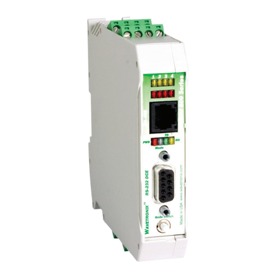
Physical Features
The Click 512 is based upon the Click 500 platform, so it has the same physical features as the Click 500.
WX-501-0537 • 01.22
1 of 14
Advertisement
Table of Contents

Related Manuals for Wavetronix Click 512

Summary of Contents for Wavetronix Click 512
- Page 1 Communication between the Click 512 and Click Supervisor is easy to set up and use. Physical Features The Click 512 is based upon the Click 500 platform, so it has the same physical features as the Click 500. WX-501-0537 • 01.22...
-
Page 2: Communication Ports
RS-485 top screw terminal connection / front RJ-11 jack connection port ■ The back of the Click 512 features a 5-position connector that plugs into a T-bus connector and provides power and RS-485 communication to the device. It also passes RS-485 communication to all other devices on the T-bus. -
Page 3: Configuration Features
Push-button If the Click 512 receives data via one port it will forward (transmit) the data to the other ports. However, only the RD (yellow) light will flicker in this case. The TD (green) light is reserved for data originating from the Click 512. -
Page 4: Operating Modes
Navigating the Menu via the Push-Button The menu is navigated via the push-button using hold and press actions: Hold – Pressing and then holding for at least 1½ seconds allows you to enter the Click 512 mode selection process. ■... - Page 5 In Run mode, when the Click 512 triggers an output on channel 1 (or 2), the digital output DO1 (or DO2) on the bottom of the device is closed. If you are using a Click 104/112/114, the top/front RS-485 port of the Click 512 sends a message to the attached contact closure device.
- Page 6 ■ The length-based classification group is 2 ■ The Click 512 sends a heartbeat message approximately every ten seconds. The following text string illustrates the heartbeat or check command that is sent out: 2014:01:14,20:58:45.849,00,0000.0,0000.0,00000000,0000.0,00 The text string contains the following information: The date is January 14, 2014 ■...
- Page 7 Note. The 35-byte serial communication delay from the sensor to the Click 512 is 3 ms at 115.2 kbps. The 9-byte serial communication delay from the Click 512 to the Click 104/112/114 is 2 ms. This is a total of 0.005 seconds of additional delay (not depicted in preceding graph).
- Page 8 feet between the location of the SmartSensor HD and the warning sign. In order to trigger at a point upstream of a sign: 1. Select the Automatic (English) configuration options. 2. Specify the corresponding setback distance in feet. In this case, the setback distance is from the location of the SmartSensor HD unit to the selected trigger point (upstream of the warning sign).
- Page 9 4. Output is deactivated at the end of the duration. Note. In run mode, it is now possible to configure the Click 512 thresholds and other settings using Click Supervisor without changing to Device Setup Mode. This allows the settings to be updated remotely. For remote management, an IP connection via a Click 301 (or equivalent device) needs to be available via the RS-232 top port.
-
Page 10: Computer Configuration
The Backups option can be used to read configurations that have previously been saved to file. Expert The Expert driver allows you to configure the Click 512. The driver is divided into two tabs, System and 512. The System tab is divided into three subtabs: General, Comm, and Autobaud. - Page 11 Setting Description Module Shows the name of the Click device. Driver Names the driver you are currently working with. Description Shows a description of the device being configured. This is only for your information and does not affect the operation of the device. Location Displays the location of the device being configured.
- Page 12 Setting Description Command Allows you to set the command sent from the device during the autobaud process. This option is currently not available. Response Shows the response the device is expecting from the above command. This option is currently not available.
- Page 13 There are nine other tabs you can access. They correspond to the eight possible contact closure outputs the Click 512 can be configured to deal with. The other eight tabs are labeled O1 through O8. These tabs allow you to configure the following for each alarm: the lanes affected, over speed and under speed thresholds, length thresholds, the duration of the contact closure, and the delay between detection and output.
- Page 14 © 2022 Wavetronix LLC. All rights reserved. Protected in the US by patents viewable at www.wavetronix.com/en/legal. Protected by Canadian Patent Nos. 2461411; 2434756; 2512689; and European Patent Nos. 1435036; 1438702; 1611458. Other US and international patents pending. Wavetronix, SmartSensor, Click, Command and all associated logos are trademarks of Wavetronix LLC. All other product or brand names as they appear are trademarks or registered trademarks of their respective holders.
Need help?
Do you have a question about the Click 512 and is the answer not in the manual?
Questions and answers