Table of Contents
Advertisement
Quick Links
Advertisement
Table of Contents

Related Manuals for Humboldt HM-4165

Summary of Contents for Humboldt HM-4165
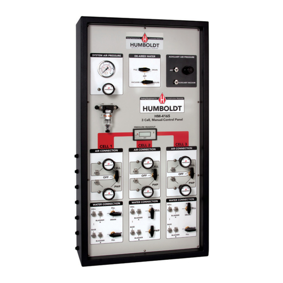
- Page 1 03.11 HM-4165 3-Cell Manual Control Panel...
-
Page 3: Installation
INSTALLATION The HM-4165 is a simple bench mounted system, which requires no fixed mounting. PANEL MOUNTING A pair of supporting feet is supplied with the panel so that it can be bench mounted and remain stable. - Page 4 are for de-aerated water return from the de-airing tank, tap water going to the de-airing tank, and air/vacuum to the de-airing tank respectively. On the face of the panel are the connections for air pressure outputs to the HM-4151A Bladder Air/Water Cylinders for cell pressure and back pressure, tap water and de-aerated water for the bladder cylinders, automatic volume change, and the triaxial cell.
-
Page 5: Electrical Connection
which connects to the volume change device. This adapter is supplied with the panel. TRIAXIAL CELL CONNECTION The triaxial cell has compression fittings on the front as shown in Figure 4. The cell connection on the triaxial cell connects to the water connection at the Cell connection on the front of the panel. -
Page 6: Pressure Gauges
AIR/WATER CONTROL VALVES There are several control valves on the panel for on/off operation of the air and water control. There are two valves under the De-Airing Tank heading (Figure 6). These valves control flow of water to and from the de-airing tank and air or vacuum to the tank. -
Page 7: Air Filter
AIR FILTER There is an in-line air filter which filters the incoming air from the compressed air source. It also traps water and other fluids in the line. MAINTENANCE There is very little maintenance required. The digital gauge operates with AC power. If the gauge fails to operate, first check the transformer to determine if it is operational. - Page 8 Figure 2...
- Page 9 LOOSEN JAM NUT PRIOR TO ADJUSTING AIR PRESSURE PUSH DOWN TO RELEASE CONNECTOR Figure 3 FIGURE 3 AIR BLEED VALVE PRESSURE TRANSDUCER TO BASE TO CELL Figure 4 Triaxial Cell FIGURE 4 TRIAXIAL CELL...
- Page 10 Figure 5 Figure 5 Figure 5B...
- Page 11 TURN KNOB LEFT TO APPLY VACUUM TO TURN KNOB LEFT DE-AIRING TANK TO FILL DE-AIRING TANK WITH TAP WATER TURN KNOB RIGHT TO APPLY PRESSURE TO TURN KNOB RIGHT TO ASSIST DRAINING DRAIN DE-AIRING TANK OF DE-AIRING TANK DE-AIRED WATER FILL DRAIN VACUUM...
-
Page 12: Water Connection
WATER CONNECTION TURN KNOB UP FILL CELL TO FILL CELL AND BLADDER CYLINDER "A" WITH TAP WATER CELL BLADDER DRAIN TURN KNOB DOWN TO DRAIN CELL AND BLADDER BASE BLADDER FILL TURN KNOB DOWN TO FILL CELL AND BLADDER CYLINDER "B" WITH DE-AERATED WATER FIGURE 8... - Page 13 Wilkerson Lubricators and Filters Installation & Service Instructions: Pneumatic Division 1M103G Miniature Series Richland, Michigan 49083 Micro-Mist Lubricators & Particulate Filters 269-629-5000 ISSUED: November, 2003 Supersedes: September, 2000 Doc.# 1M103, ECN# 030539, Rev. 8 In new installations, it is good practice to “wet down” the inside diameter of WARNING piping and/hose with oil before making final connections.
- Page 16 Warranty Humboldt Mfg. Co. warrants its products to be free from defects in material or workmanship. The exclusive remedy for this warranty is Humboldt Mfg. Co., factory replacement of any part or parts of such product, for the warranty of this product please refer to Humboldt Mfg.
Need help?
Do you have a question about the HM-4165 and is the answer not in the manual?
Questions and answers