
Related Manuals for Avalue Technology OFM-21W00


Summary of Contents for Avalue Technology OFM-21W00
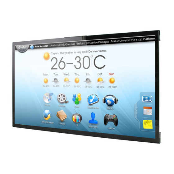
- Page 1 OFM-21W00 21.5” Full-HD Open frame PCAP Touch Monitor Quick Reference Guide Ed – 24 May, 2021 Copyright Notice Copyright 2021 Avalue Technology Inc., ALL RIGHTS RESERVED. Part No. E2017OM21A0R...
- Page 2 (2) Use only shielded cables to connect I/O devices to this equipment. (3) Changes or modifications not expressly approved by the party responsible for compliance could void the user’s authority to operate the equipment. 2 OFM-21W00 Quick Reference Guide...
- Page 3 RF exposure compliance, in order to comply with RF exposure limits established in the ANSI C95.1 standards, the distance between the antennas and the user should not be less than 20 cm. OFM-21W00 Quick Reference Guide...
- Page 4 “CAUTION - Use a power cord that matches the voltage of the power outlet, which has been approved and complies with the safety standard of your particular country.” “WARNING – To avoid risk of electric shock, this equipment must only be connected to a supply mains with protective earth.” 4 OFM-21W00 Quick Reference Guide...
-
Page 5: Table Of Contents
1.5.1 Front and Rear side ........................11 1.6 Panel Mounting ......................12 1.7 Wall Mounting......................25 Hardware Configuration ................... 37 OFM-21W00 connector mapping ................. 38 2.1.1 VGA connector (VGA) ........................ 38 OSD Key Setting ....................39 2.2.1 OSD Key Function: ........................39 2.2.2... -
Page 6: Getting Started
Place all electronic components in a static-dissipative surface or static-shielded bag when they are not in the chassis. 1.2 Packing List 1 x OFM-21W00 Industrial Touch Monitor 6 OFM-21W00 Quick Reference Guide... -
Page 7: System Specifications
12V DC in (optional 9~36V) Power Connector 12V DC jack in Type (Option for wide voltage 9~36V DC jack & phoenix connector in) Dimension 501.88 x 296.2 x 53.4 mm Weight 4.1 Kg Color Silver Fanless Fanless Reliability OFM-21W00 Quick Reference Guide... - Page 8 Reference ISTA 2A, Method : IEC-60068-2-32 Test:Ed Test Ea : Drop Test Drop Test 1 Test phase : One corner, three edges, six faces 2 Test high : 96.5cm 3 Package weight : 5Kg 4 Test drawing 8 OFM-21W00 Quick Reference Guide...
- Page 9 4-feet drop resistance without package MIL-STD-810G Operating 0°C ~ 50°C (32°F ~ 122°F) Temperature Operating 40°C @ 95% Relative Humidity, Non-condensing Humidity Storage -20°C ~ 60°C (-4°F ~ 140°F) Temperature Note: Specifications are subject to change without notice. OFM-21W00 Quick Reference Guide...
-
Page 10: System Overview
9~36V DC-in (Optional) Connectors Label Function Note DP connector HDMI HDMI connector VGA connector USB(B) for Touch USB(B) connector for Touch Mic-in Mic-in audio jack DC in(12V) DC power-in connector DC in(9~36V) DC power-in connector 10 OFM-21W00 Quick Reference Guide... -
Page 11: System Dimensions
Quick Reference Guide 1.5 System Dimensions 1.5.1 Front and Rear side (Unit: mm) OFM-21W00 Quick Reference Guide 11... -
Page 12: Panel Mounting
OFM-21W00 1.6 Panel Mounting Panel mount is the solution for mounting OFM into the opening of wall (or cabinet). The dimension of opening is as below: (Opening dimension) (Panel thickness) (Installation surface) (Unit: mm) 12 OFM-21W00 Quick Reference Guide... - Page 13 Quick Reference Guide Step1. Insert and fasten 10 pcs Hexagon Studs on each side of the OFM-21W00 Panel Bracket. Hexagon Stud OFM-21W00 Item Part Name Quantity OFM-21W00 Quick Reference Guide 13...
- Page 14 OFM-21W00 Step2. Assemble the 2pcs Bracket-RL on the left and right sides of the OFM-21W00 bracket by fastening 4 pcs screws on each side. Screw Bracket-RL Item Part Name Quantity 14 OFM-21W00 Quick Reference Guide...
- Page 15 Quick Reference Guide Step3. Assemble the Front Bracket to OFM-21W00 and fasten 10 pcs screws on the corresponding Hexagon Studs. Front Bracket Screw Item Part Name Quantity OFM-21W00 Quick Reference Guide 15...
- Page 16 OFM-21W00 Step4. Assemble the 6pcs Panel kit Brackets on the Front Bracket and fasten the 16 pcs screws to the corresponding holes. Screw Panel kit Bracket Item Part Name Quantity 16 OFM-21W00 Quick Reference Guide...
- Page 17 Quick Reference Guide (outside the wall (or cabinet) opening) Step5. Embed the OFM-21W00 semi-finished product into the wall (or cabinet) opening. Wall Item Part Name Quantity OFM-21W00 Quick Reference Guide 17...
- Page 18 Step6. Fasten the Panel mount screw*12 to the Panel mount kit bracket*12 (as shown in Figure 6-1), and then attach them to the Panel Kit Bracket*6 fixing slots. Figure 6-1 Panel mount Screw Panel Mount Kit Bracket Panel Kit Bracket Item Part Name Quantity 18 OFM-21W00 Quick Reference Guide...
- Page 19 Quick Reference Guide OFM-21W00 Quick Reference Guide 19...
- Page 20 Step7. Fasten the Panel mount screw*12 against the wall, so that the entire module can be secured by the Panel mount screws and Panel mount kit brackets. Panel mount Screw Wall Item Part Name Quantity 20 OFM-21W00 Quick Reference Guide...
- Page 21 Quick Reference Guide (The diagram is demonstrated by OFM-21W00, but the concept “the entire module can be secured by fastening the Panel mount screws against the wall” is the same) OFM-21W00 Quick Reference Guide 21...
- Page 22 OFM-21W00 Step8. Paste the 2 pcs U Plates on the Front Bracket to complete installation. U Plate Front Bracket Item Part Name Quantity 22 OFM-21W00 Quick Reference Guide...
- Page 23 Quick Reference Guide Step9. Paste the Decoration Plate on the U Plate to complete installation. Decoration Plate U Plate Item Part Name Quantity OFM-21W00 Quick Reference Guide 23...
- Page 24 OFM-21W00 24 OFM-21W00 Quick Reference Guide...
-
Page 25: Wall Mounting
Quick Reference Guide 1.7 Wall Mounting Wall mount is the solution for mounting OFM into the wall. Size of the opening: (Opening dimension) (Wall box installation dimension) (Installation surface) (Unit: mm) OFM-21W00 Quick Reference Guide 25... - Page 26 OFM-21W00 Screw hole location: (Unit: mm) 26 OFM-21W00 Quick Reference Guide...
- Page 27 Step1. Install the 21” Wall Box and fix it on the wall, and use suitable screws to lock the wall box (the screws can be purchased according to actual needs) Wall box Item Part Name Quantity OFM-21W00 Quick Reference Guide 27...
- Page 28 OFM-21W00 Step2. Assemble the 2pcs Bracket-RL on the left and right sides of the OFM-21W00 bracket by fastening 4 pcs screws on each side Screw Bracket-RL OFM-21W00 Item Part Name Quantity 28 OFM-21W00 Quick Reference Guide...
- Page 29 Quick Reference Guide Step3. Fasten 10 pcs Hexagon Studs on each side of the OFM-21W00 Bracket. Hexagon Stud BCX11_156_ASSY Item Part Name Quantity OFM-21W00 Quick Reference Guide 29...
- Page 30 OFM-21W00 Step4-1. Assemble the Front bracket to OFM-21W00, and fasten 14 pcs screws to the 10 corresponding Hexagon Studs locations and 4 Bracket R/L locations. Step4-2. Fasten the 3 pcs wall mount kit to the top of the Front bracket with 6pcs screws Step4-3.
- Page 31 Quick Reference Guide OFM-21W00 Quick Reference Guide 31...
- Page 32 OFM-21W00 32 OFM-21W00 Quick Reference Guide...
- Page 33 Quick Reference Guide Step5. Fasten the Ground wire with 2 screws on the ground screw holes of Front bracket and Wall box. Ground wire Screw Front bracket Wall box Item Part Name Quantity OFM-21W00 Quick Reference Guide 33...
- Page 34 OFM-21W00 Step6. Wrap the Kensington lock (option) around the hole in the Front bracket and attach the lock to the keyhole in the Wall box. Kensington lock Front bracket Wall box Item Part Name Quantity 34 OFM-21W00 Quick Reference Guide...
- Page 35 Quick Reference Guide Step6-1. Store the Ground wire and Kensington lock in the Wall box and embed the OFM-21W00 semi-finished product into the wall (Wall Box). Step6-2. Paste the Decoration Plate on the Front bracket to complete installation. PC bezel...
- Page 36 OFM-21W00 36 OFM-21W00 Quick Reference Guide...
-
Page 37: Hardware Configuration
Quick Reference Guide 2. Hardware Configuration Note: If you need more information, please visit our website: http://www.avalue.com.tw OFM-21W00 Quick Reference Guide 37... -
Page 38: Ofm-21W00 Connector Mapping
OFM-21W00 2.1 OFM-21W00 connector mapping 2.1.1 VGA connector (VGA) Signal PIN Signal PIN Signal GREEN DDCDAT BLUE HSYNC VSYNS DDCCLK 38 OFM-21W00 Quick Reference Guide... -
Page 39: Osd Key Setting
Quick Reference Guide 2.2 OSD Key Setting 2.2.1 OSD Key Function: OFM-21W00 Quick Reference Guide 39... -
Page 40: Osd Key Tree Table
0 - 100 0 - 100 0 - 100 0 - 100 0 - 100 0 - 100 DEMO / TYPE1 / TYPE2 / TYPE3 / TYPE4 / TYPE5 Color Format / YUV (VGA signal only) 40 OFM-21W00 Quick Reference Guide... - Page 41 Into test mode: No Signal input, then press menu key + right (up) key at the same time. Release test mode: Signal input will release test mode. Hot Key: Down/Backlight-, UP/Backlight+, Exit/Auto adjust(no auto gain) OFM-21W00 Quick Reference Guide 41...
Need help?
Do you have a question about the OFM-21W00 and is the answer not in the manual?
Questions and answers