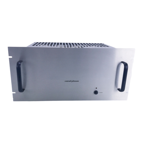
Summary of Contents for Conrad-johnson design MV45A
- Page 1 OWNER'S MANUAL MV45A AND MV75A VACUUM TUBE POWER AMPLIFIERS conrad-johnson design, inc. (703) 698-8581...
- Page 2 Thank you for your considered purchase of a conrad-johnson vacuum tube amplifier. In it, you have acquired one of the finest pieces of music reproduction equipment available today. You will find your amplifier capable of reproducing with great accuracy the dynamics, tonalities and textures of a live musical performance. The design and materials have been carefully selected to assure enduring excellence.
- Page 3 4. Where permitted by law, conrad-johnson design's liability shall be limited to that set forth in this warranty. No other warranty of any kind, expressed or implied, is made by conrad-johnson design, inc., and all implied warranties, including...
- Page 4 Factory service will be offered at reasonable rates. • Transferable warranty - conrad-johnson design guarantees its products, not the owner. Should you decide to sell the product, the warranty may be transferred to the new owner. (See Registering the Warranty.)
-
Page 5: Circuit Design
Accordingly, the audio circuits of the MV45A/MV75A amplifiers are remarkably straight-forward. A single triode input amplifier is direct coupled (MV75A) or RC coupled (MV45A) to a cathode coupled differential phase inverter made up of high current triodes to provide balanced, low impedance drive to the push-pull output stage. -
Page 6: Installation
To minimize hum pickup, keep the unit well away from the preamplifier and turntable and route power cords away from input cables. THE MV45A/MV75A IS TO BE OPERATED ONLY ON AC LINE VOLTAGE OF 108 TO 125 VOLTS (Also available wired for 100 volt or 230 volt, 50/60 Hz). - Page 7 Each component in your system is either phase correct (non-inverting) or phase inverting . If you know the phase of each component in your system (your MV45A or MV75A is phase correct) then correct absolute phase is obtained by the following...
- Page 8 If the number of phase inverting components is either none, or even, then simply wire the speakers in a phase correct manner (amplifier C to speaker "-", amplifier 4, 8, or 16 to speaker "+'. If the number of phase inverting components is odd, then one more inversion should be added.
-
Page 9: Tube Replacements
TUBE REPLACEMENTS The MV45A/MV75A amplifiers each use seven vacuum tubes of three different types. Each type has been carefully chosen for its circuit application. It is well known that tubes of a given type vary sonically depending on the manufacturer. We have chosen the brands of tubes that we supply based on extensive auditioning of available brands. - Page 10 Tube locations: Tube complement: MV75A MV45A 5751 5751 V2,V3 6FQ7/6CG7 12AT7 V4 - V7 6550 6CA7/EL34...
- Page 11 ADJUSTING OUTPUT TUBE BIAS Biasing the amplifier is a simple procedure that can readily be done by the owner. Only a screwdriver is required. After replacing the tubes, the amplifier should be connected to a load (your loudspeakers will work fine) and there should be no signal applied to the amp.
-
Page 12: Specifications
Input Impedance: 100k ohms Dimensions: 15 x 10½ x 9" Weight: 43 lbs. MV45A Power: 45 watts per channel, minimum RMS at 4, 8, or 16 ohm from 30Hz to 15kHz, with no more than 1% total harmonic distortion or intermodulation distortion. - Page 13 An LED adjacent to the fuseholder will light to indicate a blown fuse. Should the fuse blow, the output tubes in that channel are suspect and should be replaced. Fuses: MV75A MV45A ac line: 7 amp slow blow 5 amp slow blow output stage:...
- Page 14 The amplifier should be shipped without its rackplate and cover. To ship the amplifier, MV45A: remove the protective cover by removing two screws on each side of the chassis. Next remove and separately box the tubes in their individual boxes.


Need help?
Do you have a question about the MV45A and is the answer not in the manual?
Questions and answers