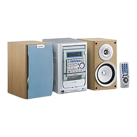
Aiwa XR-M130 Service Manual
Compact disc stereo system
Hide thumbs
Also See for XR-M130:
- Service manual (40 pages) ,
- Service manual (46 pages) ,
- Wiring diagram (23 pages)

Related Manuals for Aiwa XR-M130


Summary of Contents for Aiwa XR-M130
- Page 1 XR-M130 XR-M150 SERVICE MANUAL COMPACT DISC BASIC TAPE MECHANISM: 2ZM-1 R8NF STEREO SYSTEM BASIC CD MECHANISM: 3ZG-3 E2NF REMOTE SYSTEM CONTROLLER XR-M130 RC-AAT11 XR-M150 S/M Code No. 09-006-426-2R1...
-
Page 2: Specifications
SPECIFICATIONS <FM Tuner section> <Compact disc player section> Tuning range 87.5 MHz to 108 MHz Laser Semiconductor laser (λ =780 nm) Usable sensitivity(IHF) 13.2 dBf D-A converter 1 bit dual Antenna terminals 75 ohms (unbalanced) Signal-to-noise ratio 75 dB (1 kHz, 0 dB) Harmonic distortion 0.1 % (1 kHz, 0 dB) <AM Tuner section>... -
Page 3: Protection Of Eyes From Laser Beam During Servicing
PROTECTION OF EYES FROM LASER BEAM DURING SERVICING CAUTION This set employs laser. Therefore, be sure to follow carefully the instructions below when servicing. Use of controls or adjustments or performance of proce- dures other than those specified herin may result in WARNING!! hazardous radiation exposure. -
Page 4: Electrical Main Parts List
ELECTRICAL MAIN PARTS LIST REF. NO. PART NO. KANRI DESCRIPTION REF. NO. PART NO. KANRI DESCRIPTION C112 87-010-263-080 CAP,E 100-10 M 11L SME C113 87-010-403-080 CAP,E 3.3-50 M 11L SME 87-070-127-110 IC,LC72131D C114 87-010-374-080 CAP,E 47-10 M 11L SME 87-A20-913-010 IC,LA1837NL C115 87-A11-007-080... - Page 5 REF. NO. PART NO. KANRI DESCRIPTION REF. NO. PART NO. KANRI DESCRIPTION C612 87-010-545-080 CAP,E 0.22-50 M 11L SME C340 87-010-197-080 C-CAP,S 0.01-25 K B C2012 C613 87-010-545-080 CAP,E 0.22-50 M 11L SME C341 87-010-263-040 CAP,E 100-10 M 11L SME C614 87-010-545-080 CAP,E 0.22-50 M 11L SME...
- Page 6 REF. NO. PART NO. KANRI DESCRIPTION REF. NO. PART NO. KANRI DESCRIPTION C032 87-010-374-080 CAP,E 47-10 M 11L SME FC101 87-033-213-080 FUSE CLAMP,PFC5000<LH> C033 87-010-401-080 CAP,E 1-50 M 11L SME FC102 87-033-213-080 FUSE CLAMP,PFC5000<LH> C034 87-010-182-080 C-CAP,S 2200P-50 K B C2012 PR101 87-026-690-080 FUSE,5A 125V 251<U>...
-
Page 7: Chip Resistor Part Code
REF. NO. PART NO. KANRI DESCRIPTION REF. NO. PART NO. KANRI DESCRIPTION C784 87-012-286-080 CAP, U 0.01-25 RELAY C.B C785 87-010-401-080 CAP, ELECT 1-50V C786 87-010-401-080 CAP, ELECT 1-50V CN301 88-CL4-701-010 0E CONN ASSY,7P RPEH C789 87-012-275-080 C-CAP,U 1200P-50 B C790 87-012-275-080 C-CAP,U 1200P-50 B... -
Page 8: Transistor Illustration
TRANSISTOR ILLUSTRATION E C B E C B E C B E C B 2SA933 2SA1296 2SA952 2SA1318 2SC4115 2SC1815 2SD655 2SC3331 DTA144ES KTA1266 DTC114ES KTC3198 DTC144TS KTA1267 KTC3199 B C E B C E 2SA1162Y DTC114EK 2SK2158 2SB1616 2SB1370 2SC2712GR DTC114TK 2SD2478... -
Page 9: Wiring - 1 (Main)
WIRING - 1 (MAIN) - 9 -... - Page 10 SCHEMATIC DIAGRAM - 1 (MAIN / RELAY) - 10 -...
- Page 11 WIRING - 2 (TUNER) - 11 -...
- Page 12 SCHEMATIC DIAGRAM - 2 (TUNER) - 12 -...
- Page 13 WIRING - 2 (FRONT / RELAY / DECK) - 13 -...
-
Page 14: Schematic Diagram - 3 (Front / Deck)
SCHEMATIC DIAGRAM - 3 (FRONT / DECK) - 14 -... - Page 15 WIRING - 3 (CD / CD LOAD / CD DRIVER) - 15 -...
- Page 16 SCHEMATIC DIAGRAM - 4 (CD / CD LOAD / CD DRIVE ) - 16 -...
- Page 17 WIRING - 5 (PT: U) - 17 -...
- Page 18 SCHEMATIC DIAGRAM - 5 (PT: U) - 18 -...
- Page 19 WIRING - 6 (PT: LH) - 19 -...
- Page 20 SCHEMATIC DIAGRAM - 6 (PT: LH) - 20 -...
-
Page 21: Ic Block Diagram
IC BLOCK DIAGRAM - 21 -... - Page 22 FL (11-BT-179GNK) GRID ASSIGNMENT AND ANODE CONNECTION GRID ASSIGNMENT - 22 -...
- Page 23 ANODE CONNECTION - 23 -...
- Page 24 IC DESCRIPTION IC, LC876564W-5P35 Description Pin No. Pin Name I-VOL Rotary encider volume A/D input. O-LED_AUX Tuner functin LED ON/OFF output.Aux function LED ON/OFF output. I-HOLD System hold input A/D input. I-SW_TP Cassette detect switch A/D input. I-KEY2 Key 2 A/D input. I-KEY1 Key 1 A/D input.
- Page 25 Description Pin No. Pin Name O-P21/I-AS FL port P21 output/Auto stop signal input. O-P22/I-STOP FL port P22 output/Deck stop signal input. O-QSND QSND chip enable output. O-ECO Economical mode. O-LED_CD CD function LED ON/OFF output. I-TM_BASE Time base clock (8Hz) input. O-CD_ON CD ON/OFF control output.
- Page 26 IC, LA9241ML Pin No. Pin Name Description Connects to the pickup's photo diode; adding this pin to pin FIN1 generates RF signal, FIN2 and subtracting it generates FE signal. FIN1 Connects to the pickup's photo diode. Connects to the pickup's photo diode; subtracting this pin from pin F generates TE signal.
- Page 27 Pin No. Pin Name Description CV– Input for CLV error signal from DSP. RFSM Output for RF. RFS– For setting RF gain and 3T compensation constant together with RFSM. SLICE LEVEL CONTROL; output for controlling the data slice level of DSP with RF waveform.
- Page 28 IC, LC78622ED Pin No. Pin Name Description DEFI Defect detection signal (DEF) input. Test input. A pull-down resistor is built in. Must be connected to 0V. External VCO control phase comparator output. VVSS – Internal VCO ground. Must be connected to 0V. ISET PDO output current adjustment resistor connection.
- Page 29 Pin No. Pin Name Description LCHO Left channel one-bit D/A converter output. LVSS – Left channel one-bit D/A converter ground. Must be connected to 0V. RVSS – Right channel one-bit D/A converter ground. Must be connected to 0V. RCHO Right channel one-bit D/A converter output. RVDD –...
- Page 30 IC, LC72131D Pin No. Pin Name Description X-IN A crystal oscillator (7.2MHz) is connected between these pins. X-OUT – Not used. To enable the IC. Active "H". (M38B57MC-P214FP / M38B57MCH-P226F) Digital data input from CPU when relevant key is operated. Active "H". To clock in the data DI.
- Page 31 ADJUSTMENT < TUNER SECTION > 1. Clock Frequency Check 5. FM Tracking Check Settings : • Test point : TP2 (CLK) Settings : • Test point : TP6(Lch), TP7(Rch) Method : Set to MW 1710kHz and check that the test Method : Set to FM 98.0MHz and check that the test point is 2160kHz ±...
-
Page 32: Mechanical Exploded View
MECHANICAL EXPLODED VIEW 1 / 1 - 32-... -
Page 33: Mechanical Parts List
MECHANICAL PARTS LIST 1 / 1 REF. NO. PART NO. KANRI DESCRIPTION REF. NO. PART NO. KANRI DESCRIPTION 1 82-ZM1-264-010 LVR,EJECT R 21 86-NF9-224-010 SPR-C,LOCK 2 88-CL4-215-010 CUSH,FOOT FR 22 87-NF4-217-110 HLDR,LOCK 2 3 8A-CL9-047-010 BOX,CASS H<LH> 23 87-NF8-220-010 DMPR,150 3 8A-CL9-046-010 BOX,CASS U<U>... -
Page 34: Tape Mechanism Exploded View
TAPE MECHANISM EXPLODED VIEW 1 / 1 P.C.B HLDR,IC CAPSTAN CAPSTAN HLDR,MOTOR P.C.B HLDR WIRE 3 - 34 -... -
Page 35: Tape Mechanism Parts List
TAPE MECHANISM PARTS LIST 1 / 1 REF. NO. PART NO. KANRI DESCRIPTION REF. NO. PART NO. KANRI DESCRIPTION 1 82-ZM1-327-310 CHAS ASSY,RM 31 82-ZM1-224-410 LVR,FR 2 82-ZM1-258-210 SPR-T,PINCH L 32 82-ZM1-227-310 LVR,TRIG 3 82-ZM1-341-210 LVR ASSY,PINCH L2 33 82-ZM1-305-210 SPR-E,TRIG 2 4 82-ZM1-266-310 LVR,DIR... -
Page 36: Cd Mechanism Exploded View
CD MECHANISM EXPLODED VIEW 1 / 2 CUSH-G, MAIN A CUSH-G, MAIN A 3ZG2 MOTOR-2 C.B - 36 -... - Page 37 CD MECHANISM PARTS LIST 1 / 2 REF. NO. PART NO. KANRI DESCRIPTION REF. NO. PART NO. KANRI DESCRIPTION 1 83-ZG3-224-310 HLDR,M2 2 83-ZG3-228-610 CHAS,L6 3 83-ZG3-208-010 PULLEY,MOTOR 4 83-ZG3-213-010 LVR,SW 5 83-ZG3-209-610 CAM,SLIDE 6 83-ZG3-207-010 GEAR,TRAY 7 83-ZG3-204-210 GEAR,C 8 83-ZG3-205-010 GEAR,D 9 83-ZG3-217-010...
- Page 38 CD MECHANISM EXPLODED VIEW 2 / 2 P.C.B CD MECHANISM PARTS LIST 2 / 2 REF. NO. PART NO. KANRI DESCRIPTION 1 83-ZG2-243-210 CHAS ASSY,SHT 2 83-ZG2-235-010 GEAR,A3 3 83-ZG2-205-210 GEAR,B 4 83-ZG2-236-010 GEAR MOTOR 3 5 83-ZG2-253-010 SHAFT,SLIDE 5 6 87-A90-836-010 PICKUP,KSS-213F 8 83-ZG2-227-210...
- Page 39 2–11, IKENOHATA 1–CHOME, TAITO-KU, TOKYO 110, JAPAN TEL:03 (3827) 3111 9820572 0251431 9630472 Printed in Singapore...
Need help?
Do you have a question about the XR-M130 and is the answer not in the manual?
Questions and answers