Table of Contents
Advertisement
Quick Links
DIN Mounted Gateway
SignalFire Part Numbers: GWDIN, GWDIN-ENET
DIN Mounted Gateway
SignalFire Part Numbers: GWDIN, GWDIN-ENET
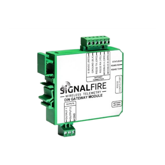
The SignalFire DIN Gateway has the following features:
-
RS485 connection to Modbus client device
-
Optional Modbus-TCP Ethernet interface module
-
Wide range DC power input. 6 to 36VDC
-
Two open collector digital outputs
-
DIN rail mount
-
Collects and caches Modbus data from all SignalFire remote nodes
-
Provides configuration and status registers for remote configuration and status monitoring
-
RP-SMA antenna port for connection to external 900MHz antenna
-
Stores up to 4700 register values from any combination of remote nodes
-
Supports transparent Modbus mode
-
Internal Remote Shut Down (RSD) logic control option
-
Modbus register re-mapping
-
Remote configuration of SignalFire devices through an Ethernet gateway connection
-
Remote sensor configuration (PACTware and RadarMaster)
-
Radio is FCC and IC approved
-
AES 128bit Encryption
-
Class 1 Division 2 Area certification pending
Rev 1.15
Interface Manual
Interface Manual
SignalFire Telemetry
1
Advertisement
Table of Contents

Related Manuals for SIGNAL FIRE GWDIN

Summary of Contents for SIGNAL FIRE GWDIN
-
Page 1: Signalfire Part Numbers: Gwdin, Gwdin-Enet
Interface Manual DIN Mounted Gateway Interface Manual SignalFire Part Numbers: GWDIN, GWDIN-ENET DIN Mounted Gateway SignalFire Part Numbers: GWDIN, GWDIN-ENET The SignalFire DIN Gateway has the following features: RS485 connection to Modbus client device Optional Modbus-TCP Ethernet interface module Wide range DC power input. 6 to 36VDC... -
Page 2: Table Of Contents
Table of Contents SignalFire Part Numbers: GWDIN, GWDIN-ENET __________________________________ 1 SignalFire Part Numbers: GWDIN, GWDIN-ENET __________________________________ 1 Specifications ______________________________________________________________ 4 Connections and Components _______________________________________________________________ 5 DIN Gateway Connections_________________________________________________________________________ 5 Optional Ethernet Gateway Connections _____________________________________________________________ 5 Status LEDs _____________________________________________________________________________________ 6 Operation _______________________________________________________________________________ 6... - Page 3 RS485 Details _____________________________________________________________ 23 Network Map _____________________________________________________________ 23 Gateway Event Log _________________________________________________________ 24 Saving the Gateway Log _________________________________________________________ 24 Modbus Gateway Register Map ______________________________________________ 25 Coils _________________________________________________________________________________________ 25 Holding Registers _______________________________________________________________________________ 26 Revision History _________________________________________________________________________ 31 Hazardous Location Certification ____________________________________________________________ 32 Rev 1.15 SignalFire Telemetry...
-
Page 4: Specifications
-40°C to +85°C Radio 902-928MHz ISM Band, FHSS radio, 500mW, RP-SMA connector. FCC ID: W8V-GWDIN, IC: 8373A-GWDIN Compliance Certified for use in Class I, Division 2 groups C, D, T5. EXi [EXi] FCC/IC Certified. Certified to CSA C22.2 2015 No. 213. -
Page 5: Connections And Components
Connections and Components DIN Gateway Connections The DIN Gateway has a 6-position pluggable terminal block for power and serial communications. The connections are as follows: Terminal Name Connection 6-36VDC (RED) Positive Power (6 to 36 VDC) GROUND (BLK) Ground RS232 TX (ORG) RS-232 Debug TX, 9600 Baud (Only used with Ethernet Interface module) RS232 RX (YEL) RS-232 Debug RX, 9600 Baud (Only used with Ethernet Interface module) -
Page 6: Status Leds
Status LEDs The DIN Gateway has three LED Available for field diagnostics. The RS485 TX/RX LEDs will blink in response to RS485 traffic, the status LED is described below. STATUS LED Description Slow Flash (3 second pause) System is running and in communication with radio network Fast Flash (0.5 second pause) System is running but no network found Solid On... -
Page 7: Remote Modbus Stick Node Re-Scan
Remote Modbus Stick Node Re-Scan It is possible to cause a remote Modbus Stick to re-scan for attached Modbus devices by writing to one of the gateway’s configuration registers. This is useful to discover a Modbus device that is added to an existing Modbus node. The scan may be initiated by one of the two methods. - Page 8 Using the SignalFire Toolkit The SignalFire Toolkit application can be downloaded at www.signal- fire.com/customer. After installation, launch the software and the main toolkit window will open: Select the COM port associated with the DIN Gateway and click “Auto-Detect Device on COM Port.” This will open the device configuration window, where all device settings can be configured.
-
Page 9: Encryption
Network Setting The network is set using the SignalFire Toolkit. There can only be one Gateway per network/group/encryption combination, otherwise they will conflict. In a system with multiple Gateways, each Gateway must be on a separate network/group/encryption combination. The network, network group, and corporate ID/encryption key settings must match those of its nodes for them to communicate. -
Page 10: Checking Remote Nodes
Checking Remote Nodes If one or more remote nodes are configured with the correct network settings, they will send their data to the gateway. Clicking Refresh List will populate the list with all connected remote nodes. The gateway displays the node type, node name (if it has been set), RSSI signal strength, check-in interval, the Time-To-Live (TTL), and the node’s radio and main firmware versions. -
Page 11: Remote Node Configuration
Remote Node Configuration The SignalFire Gateway allows configuration changes to be made to any of the connected SignalFire remote nodes wirelessly. To use this feature, access to the Gateway debug port is required. This may be accessed over a TCP/IP network using a SignalFire Ethernet Gateway module, or by a direct connection to the Gateway RS232 port. - Page 12 Make any necessary changes and click the Apply All Settings button to save the changes. When finished with the configuration, close the configuration window and then click the End button in the Gateway window to end the session. The session will also automatically time-out after 15 minutes of inactivity and the Node will resume normal operation.
-
Page 13: Firmware Upgrades
Firmware Upgrades Firmware updates for both the gateway (ARM) and the built-in radio are possible over the RS-232 debug interface using the SignalFire Toolkit, or over a remote TCP connection if an Ethernet Gateway module is used. Gateway (ARM) Firmware update steps Open the SignalFire Toolkit application. -
Page 14: Remote Shutdown (Rsd) And Local Digital Output Control
Remote Shutdown (RSD) and Local Digital Output Control The SignalFire Gateway supports Internal Logic Control capability which enables the Gateway to control output relays on SignalFire RSD sticks as well as the two digital outputs local to the Gateway. The SignalFire Gateway Stick receives data from multiple remote nodes. It can use the data from those remote nodes to set the relay output on one or more remote RSD sticks. -
Page 15: Rsd Configuration
RSD Configuration From the Gateway configuration window within the SignalFire Toolkit, go to the Settings menu and select Remote Shutdown Settings. This will open the RSD configuration window. Source Value Section The ‘Source Value’ section is used to select the source register for the logic rule. Modbus ID –... -
Page 16: Relay Control Logic Section
Relay Control Logic Section The ‘Relay Control Logic’ section is used to set the trigger thresholds for the selected source data register. Run System (Energize Relay) – Select the logic operand to use for the “energize” logic evaluation. Value – The value that the relay will be energized. Note that the energized state is the normal “operating”... -
Page 17: Destination Rsd Stick Section
Destination RSD Stick Section Modbus ID – The Modbus ID of the destination RSD Stick, or the Modbus ID of the Gateway (default 247) for the local digital outputs. Relay Channel – Select the relay or digital output channel to switch Current Relay State –... -
Page 18: Example
Example Line 1 has been configured with a source data node as a Sentinel-Analog with the loop current (in μA) as the selected register. The relay will energize when the loop current is above 1400μA (14mA) and de-energize when the loop current is below 1300μA (13mA). -
Page 19: Options
Options There are two check boxes for additional logic options. Failsafe Enabled – If this option is selected all rules must have valid data for the relay to be energized. If one or more of the nodes times-out or does not exist the relay will be de-energized. If this option is not selected, then a node that is not installed or fails to check in will be ignored and the relay will be energized using logic only from the units that are active. -
Page 20: Modbus Register Remapping
Modbus Register Remapping The gateway allows any of the remote register data to be remapped to a single block of registers available at the Gateway’s Modbus ID (default is 247). This is useful for collecting a subset of register data from multiple nodes and making it readable in a single block of registers. -
Page 21: Use Data Type Floats
Use Data Type Floats The Gateway’s Modbus Register Remapping provides an option to remap all registers to 32-bit floats. This allows the user to enter a register and its data type knowing that it will be read from the gateway via Modbus as two 16-bit registers. To use the floating-point remapping, select the ‘Use Data Type Float’... -
Page 22: Fail Mode
Fail Mode If the gateway does not have data for a remapped value it will respond with 0xFFFF, or 0x0000 for the register request, this is configurable globally with the Fail Mode settings. Modbus ID 21 isn't reporting in, fail mode set to "high" Load/Save Files The displayed remap information can be saved to a proprietary file by clicking the ‘Save to File’... -
Page 23: Output Modules
Output Modules With the purchase of a SignalFire Analog Output Module or Digital Output Module, the Gateway can directly control analog (4-20mA, 1-5V) and digital outputs. The outputs for the module can be controlled through the “Analog/Relay Output Module” window under the Settings menu. Further information on the modules can be found in their respective manuals. -
Page 24: Gateway Event Log
Gateway Event Log Starting with Gateway Firmware version 7.81 the Gateway keeps an internal log of events. The event log can be viewed from the gateway window of the ToolKit by clicking ‘View Gateway Log’ at the bottom of the window. The gateway log events such as reboots, remote nodes joining/timing out, local RSD control events, remote configuration sessions, firmware updates, and more. -
Page 25: Modbus Gateway Register Map
Modbus Gateway Register Map The SignalFire Modbus Gateway by default is assigned Modbus ID number 247. Only the Gateway status/configuration and remapped registers are read at this address. All remote node registers are read from the Modbus ID and register address of the remote node unless Modbus register remapping is used. -
Page 26: Holding Registers
Register Register Description Address Number 0151 00152 Digital Output Module 2 Relay 9 0152 00153 Digital Output Module 2 Relay 10 0153 00154 Digital Output Module 2 Relay 11 0154 00155 Digital Output Module 2 Relay 12 2034 02035 State of Digital Output 1 (0=open, 1=closed) 2035 02036 State of Digital Output (0=open, 1=closed) - Page 27 Register Register Description Address Number 1132 41133 Digital Output Module 1 Relay 2 1133 41134 Digital Output Module 1 Relay 3 1134 41135 Digital Output Module 1 Relay 4 1135 41136 Digital Output Module 1 Relay 5 1136 41137 Digital Output Module 1 Relay 6 1137 41138 Digital Output Module 1 Relay 7...
- Page 28 Register Register Description Address Number 2015 42016 Modbus ID [111-96]: Bitmask for Modbus IDs 111-96 (LSB is 96) 2016 42017 Modbus ID [127-112]: Bitmask for Modbus IDs 127-112 (LSB is 112) 2017 42018 Modbus ID [143-128]: Bitmask for Modbus IDs 143-128 (LSB is 128) 2018 42019 Modbus ID [159-144]: Bitmask for Modbus IDs 159-144 (LSB is 144)
- Page 29 Register Register Description Address Number 4001 44002 Status of Modbus ID 1: Returns 1 if device is present and 0 if not present 4002 44003 Status of Modbus ID 2: Returns 1 if device is present and 0 if not present …...
- Page 30 Register Register Description Address Number 7102 47103 Scratch Pad Register, can be used for RSD Control Logic … … … 7132 47133 Scratch Pad Register, can be used for RSD Control Logic Rev 1.15 SignalFire Telemetry...
-
Page 31: Revision History
Revision History Revision Date Changes/Updates 10/02/15 Initial Release for DIN Gateway 2/26/16 Added FCC/IC certification details 4/6/16 Added detail for Gateway digital outputs 1.4/1.5 4/18/16 Updated IC statements and added C1D2 Statements 8/3/16 Added section on encryption 1.7/1.8 9/4/2018 Updated screenshots, rewrote network/encryption, cleaned up 10/17/2018 Added RSD pulse settings and registers 1.10... -
Page 32: Hazardous Location Certification
Hazardous Location Certification The DIN Gateway Module is rated Class 1 Division 2 non-Incendive. WARNING: EXPLOSION HAZARD. DO NOT REMOVE OR REPLACE COMPONENTS UNLESS POWER HAS BEEN DISCONNECTED OR THE AREA IS FREE OF IGNITIBLE CONCENTRATIONS. AVERTISSEMENT : RISQUE D'EXPLOSION . NE PAS RETIRER OU REMPLACER LES COMPOSANTS QUE L’ALIMENTATION EST DÉBRANCHÉ... - Page 33 APPENDIX - FCC and IC Statements Changes or modifications not expressly approved by SignalFire Telemetry, Inc could void the user’s authority to operate the equipment. This device complies with Part 15 of the FCC Rules. Operation is subject to the following two conditions: (1) this device may not cause harmful interference, and (2) this device must accept any interference received, including interference that may cause undesired operation.
Need help?
Do you have a question about the GWDIN and is the answer not in the manual?
Questions and answers