Table of Contents
Advertisement
Quick Links
The SignalFire Gateway-In-A-Stick has the following features:
-
RS485 connection to Modbus client device (Optional Modbus-TCP interface module)
-
Wide range DC power input: 6-36VDC
-
Collects and caches Modbus data from all SignalFire remote devices
-
Provides configuration and status registers for remote configuration and status monitoring
-
Integrated 500mW FHSS 900MHz ISM band radio and high gain antenna
-
Stores up to 4700 register values from any combination of remote nodes
-
Supports transparent Modbus mode
-
Internal Remote Shut Down (RSD) logic control option
-
Modbus register re-mapping
-
Remote configuration of SignalFire devices through an Ethernet gateway connection
-
Remote sensor configuration (PACTware and RadarMaster)
-
AES-128 Encryption
-
Class 1 Division 2 Area certification
Rev 4.9
Interface Manual
Gateway-In-A-Stick
SignalFire Number: GWS-CBBL
SignalFire Telemetry
1
Advertisement
Table of Contents

Related Manuals for SIGNAL FIRE GWS-CBBL

Summary of Contents for SIGNAL FIRE GWS-CBBL
- Page 1 Interface Manual Gateway-In-A-Stick SignalFire Number: GWS-CBBL The SignalFire Gateway-In-A-Stick has the following features: RS485 connection to Modbus client device (Optional Modbus-TCP interface module) Wide range DC power input: 6-36VDC Collects and caches Modbus data from all SignalFire remote devices Provides configuration and status registers for remote configuration and status monitoring...
-
Page 2: Table Of Contents
Table of Contents Specifications _______________________________________________________________________________________ 4 Connections and Components _____________________________________________________________________ 5 Gateway-In-A-Stick Connections _________________________________________________________________ 5 Status LED ________________________________________________________________________________________ 5 Operation _________________________________________________________________________________________________________ 6 Remote Modbus Sticks and Sentinel-Modbus (non-sleeping radio only) Nodes ______________________________ 6 Remote Modbus Stick Node Re-Scan __________________________________________________________________________ 6 Setup _____________________________________________________________________________________________________________ 7 Optional Ethernet Gateway Connections _______________________________________________________________________ 7 Encryption ______________________________________________________________________________________________________ 9... - Page 3 Modbus Gateway Register Map ___________________________________________________________________ 25 Coils _____________________________________________________________________________________________ 25 Holding Registers _______________________________________________________________________________ 26 Revision History ____________________________________________________________________________________ 30 Hazardous Location Certification __________________________________________________________________ 31 Rev 4.9 SignalFire Telemetry...
-
Page 4: Specifications
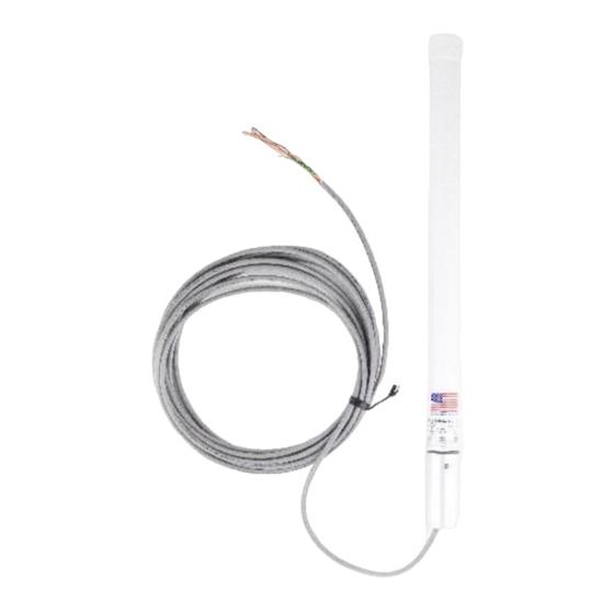
Specifications Gateway Size 20.5” overall length. 1.45” diameter Mounting ¾” Female NPT fitting Power Source 6-36VDC. 25mA @ 12VDC (average), 17mA @ 24VDC (average) Temperature Rating -40°C to +85°C Radio 902-928MHz ISM Band, FHSS radio. IC and FCC Part 15 certified Integrated 5dBi antenna. -
Page 5: Connections And Components
Connections and Components Gateway-In-A-Stick Connections The Gateway-In-A-Stick is supplied with a 6’ conductor cable. The connections are as follows: Wire Color Connection Positive Power (6 to 36 VDC) BLACK Ground GREEN RS-485 “A”, 9600 Baud BROWN RS-485 “B”, 9600 Baud ORANGE RS-232 Debug/Programming TX, 9600 Baud YELLOW... -
Page 6: Operation
Operation The Gateway-In-A-Stick supports all remote SignalFire nodes making all remote sensor data available in Modbus format. The register data from remote sensor nodes is available by requesting the remote node’s Modbus ID and register address from that node’s register map. The gateway will respond with the most recent copy of the data from the remote node. -
Page 7: Setup
Setup The Gateway-in-a-Stick requires an initial configuration over RS-232 using the SignalFire Toolkit. Connect a USB-Serial cable (can be purchased from SignalFire) between a computer and the Gateway’s DB9 port. The following items must be configured to set up a SignalFire network: Radio Network Radio Network Group Corporate ID/Encryption Key... - Page 8 Using the SignalFire Toolkit The SignalFire Toolkit application can be downloaded at www.signal-fire.com/customer. After installation, launch the software and the main toolkit window will open: Select the COM port associated with the Gateway Stick and click “Auto-Detect Device on COM Port.” This will open the device configuration window, where all device settings can be configured.
-
Page 9: Encryption
Network Setting The network is set using the SignalFire Toolkit. There can only be one Gateway per network/group/encryption combination, otherwise they will conflict. In a system with multiple Gateways, each Gateway must be on a separate network/group/encryption combination. The network, network group, and corporate ID/encryption key settings must match those of its nodes for them to communicate. -
Page 10: Checking Remote Nodes
Checking Remote Nodes If one or more remote nodes are configured with the correct network settings, they will send their data to the gateway. Clicking Refresh List will populate the list with all connected remote nodes. The gateway displays the node type, node name (if it has been set), RSSI signal strength, check-in interval, the Time-To-Live (TTL), and the node’s radio and main firmware versions. -
Page 11: Remote Node Configuration
Remote Node Configuration The SignalFire Gateway allows configuration changes to be made to any of the connected SignalFire remote nodes wirelessly. To use this feature, access to the Gateway debug port is required. This may be accessed over a TCP/IP network using a SignalFire Ethernet Gateway module, or by a direct connection to the Gateway RS232 port. - Page 12 Settings Make any necessary changes and click the Apply All button to save the changes. When finished with the configuration, close the configuration window and then click the button in the Gateway window to end the session. The session will also automatically time-out after 15 minutes of inactivity and the Node will resume normal operation.
-
Page 13: Firmware Upgrades
Firmware Upgrades Firmware updates for both the gateway (ARM) and the built-in radio are possible over the RS-232 debug interface using the SignalFire Toolkit, or over a remote TCP connection if an Ethernet Gateway module is used. Gateway (ARM) Firmware update steps Open the SignalFire Toolkit application. -
Page 14: Remote Shutdown (Rsd) Control
Remote Shutdown (RSD) Control Internal Logic Control The SignalFire Gateway supports capability which enables the Gate- way to control output relays on SignalFire RSD sticks. The SignalFire Gateway Stick receives data from multiple remote nodes. It can use the data from those remote nodes to set the relay output on one or more remote RSD sticks. -
Page 15: Rsd Configuration
RSD Configuration Settings From the Gateway configuration window within the SignalFire Toolkit, go to the Remote Shutdown Settings menu and select . This will open the RSD configuration window. Source Value Section The ‘Source Value’ section is used to select the source register for the logic rule. Modbus ID –... -
Page 16: Relay Control Logic Section
Relay Control Logic Section The ‘Relay Control Logic’ section is used to set the trigger thresholds for the selected source data register. Run System (Energize Relay) – Select the logic operand to use for the “energize” logic evaluation. Value – The value that the relay will be energized. Note that the energized state is the normal “operating” state of the relay. -
Page 17: Destination Rsd Stick Section
Destination RSD Stick Section Modbus ID – The Modbus ID of the destination Counter Stick. Relay Channel – Select the relay channel to switch Current Relay State – Shows the last value of the relay as reported to the gateway (except for IO1 module). Clicking the Update button will refresh this value. -
Page 18: Example
Example Line 1 has been configured with a source data node as a Sentinel-Analog with the loop current (in μA) as the selected register. The relay will energize when the loop current is above 1400μA (14mA) and de-energize when the loop current is below 1300μA (13mA). Note that this configuration has a 1000μA (1mA) hysteresis factor. -
Page 19: Additional Options
Additional Options There are two check boxes for additional logic options. Failsafe Enabled – If this option is selected rules must have valid data for the relay to be energized. If one or more of the nodes times-out or does not exist the relay will be de-energized. If this option is not selected, then a node that is not installed or fails to check in will be ignored and the relay will be energized using logic only from the units that are active. -
Page 20: Modbus Register Remapping
Modbus Register Remapping The gateway allows any of the remote register data to be remapped to a single block of registers available at the Gateway’s Modbus ID (default is 247). This is useful for collecting a subset of register data from multiple nodes and making it readable in a single block of registers. Up to 1500 registers can be remapped to the gateway’s Modbus ID starting at register 5000. -
Page 21: Use Data Type Floats
Use Data Type Floats The Gateway s Modbus Register Remapping provides an option to remap all registers to 32-bit floats. This allows the user to enter a register and its data type knowing that it will be read from the gateway via Modbus as two 16-bit registers. To use the floating-point remapping, select the ‘Use Data Type Float’... -
Page 22: Fail Mode
Fail Mode If the gateway does not have data for a remapped value it will respond with 0xFFFF, or 0x0000 for the register request, configurable globally with the Fail Mode settings. Modbus ID 21 isn't reporting in, fail mode set to "high" Load/Save Files The displayed remap information can be saved to a proprietary file by clicking the ‘Save to File’... -
Page 23: Rs485 Details
RS485 Details The Gateway keeps a log of any Modbus requests made to either itself or any Modbus nodes connected to it. The Modbus Transmission Log can be viewed under the Tools menu by selecting “RS485 Details”. When the Gateway is open in the ToolKit, this log will be automatically written to the Log folder. The RS485 Modbus Details window also has a ‘Send Log to Tech Support’... -
Page 24: Gateway Event Log
Gateway Event Log Starting with Gateway Firmware version 7.81 the Gateway keeps an internal log of events. The event log can be viewed from the gateway window of the ToolKit by clicking ‘View Gateway Log’ at the bottom of the window. The gateway log events such as reboots, remote nodes joining/timing out, local RSD control events, remote configuration sessions, firmware updates, and more. -
Page 25: Modbus Gateway Register Map
Modbus Gateway Register Map Only the The SignalFire Modbus Gateway by default is assigned Modbus ID number 247. Gateway status/configuration and remapped registers are read at this address. remote node registers are read from the Modbus ID and register address of the remote node unless Modbus register remapping is used. -
Page 26: Holding Registers
Register Register Description Address Number 0151 00152 Digital Output Module 2 Relay 9 0152 00153 Digital Output Module 2 Relay 10 0153 00154 Digital Output Module 2 Relay 11 0154 00155 Digital Output Module 2 Relay 12 7100 07101 RSD Force Shutdown Holding Registers Read holding registers with Modbus opcode 0x03 (Read Holding Registers) or 0x04 (Read Input Registers). - Page 27 Register Register Description Address Number 1136 41137 Digital Output Module 1 Relay 6 1137 41138 Digital Output Module 1 Relay 7 1138 41139 Digital Output Module 1 Relay 8 1139 41140 Digital Output Module 1 Relay 9 1140 41141 Digital Output Module 1 Relay 10 1141 41142 Digital Output Module 1 Relay 11...
- Page 28 Register Register Description Address Number 2019 42020 Modbus ID [175-160]: Bitmask for Modbus IDs 175-160 (LSB is 160) 2020 42021 Modbus ID [191-176]: Bitmask for Modbus IDs 191-176 (LSB is 176) 2021 42022 Modbus ID [207-192]: Bitmask for Modbus IDs 207-192 (LSB is 192) 2022 42023 Modbus ID [223-208]: Bitmask for Modbus IDs 223-208 (LSB is 208)
- Page 29 Register Register Description Address Number 5000 45001 Remapped Register 1 5001 45002 Remapped Register 2 … … … 6499 46500 Remapped Register 1500 7000 47001 RSD Event 1 Line # 7001 47002 RSD Event 1 Source Modbus ID 7002 47003 RSD Event 1 Destination Modbus ID 7003 47004...
-
Page 30: Revision History
Revision History Revision Date Changes/Updates 11/29/10 Clarified description for register 1002 Added registers and description for “transparent” Modbus mode Added detail on using SignalFire Toolkit Updated SignalFire Toolkit screenshots Added additional detail on register mapping Updated SignalFire Toolkit screenshots, added RSD control section Added Modbus ID status registers Added section of Modbus register mapping Added section on remote node configuration... -
Page 31: Hazardous Location Certification
Hazardous Location Certification The Gateway-in-a-Stick is rated Class 1 Division 2 non-Incendive. WARNING: EXPLOSION HAZARD. DO NOT REMOVE OR REPLACE COMPONENTS UNLESS POWER HAS BEEN DISCONNECTED OR THE AREA IS FREE OF IGNITIBLE CONCENTRATIONS. AVERTISSEMENT : RISQUE D'EXPLOSION . NE PAS RETIRER OU REMPLACER LES COMPOSANTS QUE L’ALIMENTATION EST DÉBRANCHÉ... - Page 32 APPENDIX - FCC and IC Statements Changes or modifications not expressly approved by SignalFire Telemetry, Inc could void the user’s authority to operate the equipment. This device complies with Part 15 of the FCC Rules. Operation is subject to the following two conditions: (1) this device may not cause harmful interference, and (2) this device must accept any interference received, including interference that may cause undesired operation.
Need help?
Do you have a question about the GWS-CBBL and is the answer not in the manual?
Questions and answers