Advertisement
Quick Links
Advertisement

Related Manuals for Durite 0-875-05


Summary of Contents for Durite 0-875-05
- Page 1 Incident Camera 0-875-05 / 0-875-15 Installation and User Guide...
-
Page 2: Table Of Contents
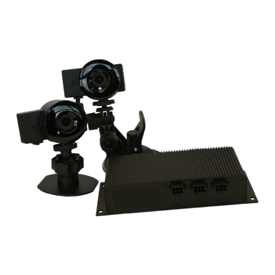
Incident Cam | Installation & User Guide In this guide In this guide In the box Important note General setup Installing the telematics device , Control Unit and Dongle Installing the camera(s) Installing the panic buUon OperaDon Commissioning your Incident Camera Guidelines for commissioning Technical specificaDons Contact details In the box Provided in the box is everything you need to install the Durite Incident Camera in your vehicle, including the telematics device, camera control unit and sufficient cables to allow the wiring to be routed around the vehicle interior as required. • Incident Camera main control unit • High definiDon camera • TelemaDcs device • Power connecDon cable with USB-A socket • Camera extension cable •... -
Page 3: General Setup
Incident Cam | Installation & User Guide General setup ... - Page 4 Incident Cam | Installation & User Guide Installing the telematics unit, Control Unit and Dongle The GPS antenna of the telmatics unit is located on the top of the device. You must install the device with the label facing the sky to ensure a good GPS fix. Find a suitable and covert locaDon under or behind the dashboard of the vehicle and fit the telematics unit in such a way that it is absolutely secure. Any potenDal wobble or tremor will cause false data to be recorded in the telemetry, possibly causing the system to not funcDon as intended. Cable Des are usually employed as part of this process. Install the control unit similarly, but in a different locaDon. The telematics unit should not be mounted in the same loca8on as the control unit, as this will prevent the correct operaDon of the system. Connect the telematics unit to the control unit using the 20-pin connector. This should click in with a firm press. Locate suitable covert connecDon points to the vehicle's wiring and idenDfy the following sources: A permanent +12V or +24V feed. Ensure that this supply is constant, irrespecDve of • whether the vehicle's igniDon is on or off. A permanent earth (such as the vehicle's chassis). •...
- Page 5 Modem is registered to a network and is Solid receiving acknowledgement ("connected") Connect the WiFi dongle to the USB-A socket on the power cable. PosiDon the dongle as high in the vehicle as is possible, away from any large wiring looms to prevent interference and to ensure the best chance of connecDvity. Discretely hide the dongle and secure it in place. Electrical tape is usually employed for this process. Connect each camera to its respecDve extension cable. Cau8on: ensure that the coloured wires which join pin match at the pins. The end of the extension cable which connects to the camera is labelled with a blue tag. Installing the extension cables with the control unit end and camera end reversed will cause the camera to not funcDon correctly. Insert the 6-pin connectors on the camera extension cable for each of the cameras you intend to install (note the “CAM1” and “CAM2” labels). If you are only installing one camera, only use the “CAM1” connecDon. Then route the extension cables to the opDmum posiDons for the installaDon of the cameras. If installing a system with both a visible light and an infrared camera, ensure that they are located and directed in the desired locaDons (in most installaDons this will be the visible light camera facing forwards out of the cabin, infrared facing inside the cabin at the driver or passengers). If the cameras are not labelled as “infrared” or “visible”, ask Durite Telema8cs for guidance when the unit is commissioned. AddiDonally, you should be able to disDnguish between the two when a video is uploaded: infrared video has a disDncDve pink/magenta Dnt. 5 of 9...
-
Page 6: Installing The Camera(S)
Incident Cam | Installation & User Guide Installing the camera(s) CAM1 should be installed facing forwards from the front windscreen to give a “driver’s eye” view of the road ahead. For cars and vans the posiDon typically used is behind the rear view mirror as shown below. Ensure that any adjustments made to the mounDng are secure to prevent the camera from DlDng or poinDng away from the intended focus area. OpDmally, forward facing cameras should be focused at an angle just below level with the road to capture the area from the front of the bonnet to the horizon. If a camera is mounted outside of the area of the windscreen cleared by the wipers, the image will be obscured during inclement weather and blurry in direct sunlight. If another camera is installed, it should be posiDoned to capture the target area as required (driver’s seat, rear interior, rear view, etc). The angle and video quality should be checked and confirmed during the commissioning process. Installing the panic buUon The small push buUon included with the kit funcDons as the system's "panic buUon". When pressed it captures the last 10 and following 5 seconds of footage from the camera and immediately uploads it to the cloud. You may need to drill a small hole in the vehicle's dashboard in order to mount the buUon. It should be located in such a posiDon where the driver can reach it without undue distracDon from controlling the vehicle. A screw arrangement on the buUon will grip the dashboard and hold it in place. The panic buUon is installed by connecDng the blue and black wires leading directly from the telematics unit to the pins on the buUon. Do not wire the blue or black to any other component, and take care not to confuse the black wire from the control unit and the black wire for the buUon. If you do not wish to install the panic buUon, ensure that the blue and black wires are secured in such a way that they do not touch, and cannot touch any other metallic component. -
Page 7: Operadon
OperaDon If correctly installed, the control unit will power up when the vehicle’s igniDon is turned on. A blue LED will display adjacent to the control unit’s POWER socket. Each installed camera will also display a small blue LED. The unit will remain powered for up to ten minutes amer the igniDon has been turned off. When powered, the WiFi dongle will display two LEDs: blue and green. In order for the Incident Camera system to funcDon correctly, both blue and green LEDs need to be illuminated conDnually. When the vehicle’s igniDon is started, it may take up to one minute for both lights to illuminate as the dongle goes through its boot process and aUempts to make a connecDon. If any other light paUern shows, you will be unable to commission your system. Ensure that you are located in an area with a good 3G data signal. If not, endeavour to move the locaDon to one. Commissioning your Incident Camera Amer installaDon, contact your support centre to confirm operaDon and file upload. For Durite customers, this will always be the Durite Support desk (0330 995 1995). All issues must be reported to the Durite Support team at the Dme of installaDon. Take care not to trigger mulDple panic videos or crash videos, as this may cause undue delay during commissioning. It is good pracDce to complete the installaDon with the baUery +12V fuse removed unDl all units are secured. This will ensure the process is more efficient. You support centre will expect to see a video from the camera on the Durite telematics portal, and will talk you through any faults which may have occurred during installaDon. Be prepared to revisit parts of your installaDon during commissioning, if requested by your support centre. -
Page 8: Guidelines For Commissioning
Incident Cam | Installation & User Guide Guidelines for commissioning Start the vehicle Ensure that all the following LEDs are illuminated: Telematics unit: orange and green. The should illuminate and then begin flashing. When first installed, the flashing should stop within five minutes and should remain steady. WiFi dongle: blue and green. Both the blue and the green should both illuminate and remain steady within one minute. Control unit: blue. Should illuminate and remain steady within one minute. Each camera: blue. Should illuminate and remain steady within one minute. If one or more of the LEDs are not illuminated, turn the vehicle's igniDon off and then wait ten minutes before conDnuing. When all LEDs are illuminated and steady, leave the vehicle's engine running for at least one minute. Press the panic buUon (if not installed, briefly touch the blue and black wires for the panic buUon together) to trigger a video. Record the following informtion and forward this to the support team as soon as possible. - Camera serial number - Registration of the vehicle - IMEI of the telematics unit If at any step the LED lights are not as described, please examine the installation and... -
Page 9: Technical Specificadons
Incident Cam | Installation & User Guide Technical specificaDons Processor: ARM Cortex-A7, Allwinner Quad core H3, 1.6GHZ Memory: 1GB RAM Internal Storage: 32GB or 64GB NAND Flash Camera sensor: 5.0MP, opDonal infrared Night Vision Video: 720p or 1080p resoluDon, up to 30FPS, 120’ viewing angle Audio: Dual mic\DSP and advanced audio enhancement OperaDng temperature: -10 to 60°C Dimensions: 60mm x 40mm x 30mm Weight: 0.05kg Contact details telematics@durite.co.uk Email: 0330 995 1995 Telephone:... - Page 10 +12V / +24V Standard Installation (Incident Cam) ignition pin 1 pin 3...
- Page 11 +12V / +24V Privacy Switch (Incident Cam) ignition pin 12 pin 3 pin 1...
- Page 12 +12V / +24V Driver ID (Incident Cam) ignition pin 11 pin 17 pin 16 pin 3 pin 1...
- Page 13 +12V / +24V Driver Feedback (Incident Cam) ignition pin 13 pin 3 pin 1...
- Page 14 +12V / +24V Temperature Probe & Card Reader (Incident Cam) ignition For first sensor in daisy chain, connect blue to black to ignition pin 11 Leave black disconnected connector For last sensor in daisy chain, leave red disconnected pin 3 pin 1...
Need help?
Do you have a question about the 0-875-05 and is the answer not in the manual?
Questions and answers