
Related Manuals for VENTOXX HARMONY


Summary of Contents for VENTOXX HARMONY
- Page 1 Instructions for installation and operation of the decentralized ventilation units with heat recovery VENTOXX HARMONY Ventoxx LLC 2021...
-
Page 2: Table Of Contents
5.1. General information 5.2. Connection of master-slave pairs and control of the fresh air heat recovery unit by remote control 5.3. Connection of the decentralized heat recovery units to the Ventoxx Twist control 5.3.1. Wiring schematics for Ventoxx Twist fans and controls…………………………………………………………………………………………………….……………….16... -
Page 3: Introduction
You have purchased a high quality decentralized heat recovery unit from the Ventoxx TM. If you just took the ventilation device out of the package, you are holding our pride and the result of many years of work in your hands. Thousands of hours of engineers' work for continuous improvement, new developments and product prototyping;... -
Page 4: Safety Instructions
2. Ventilation device 2.1. Purpose of the device Ventoxx Harmony ventilation device is a decentralized ventilation unit with heat recovery (hereinafter - recuperator). Decentralized heat recovery units are installed to provide autonomous air exchange in rooms and at the same time retain heat due to the effect of recovery. -
Page 5: Complete Set
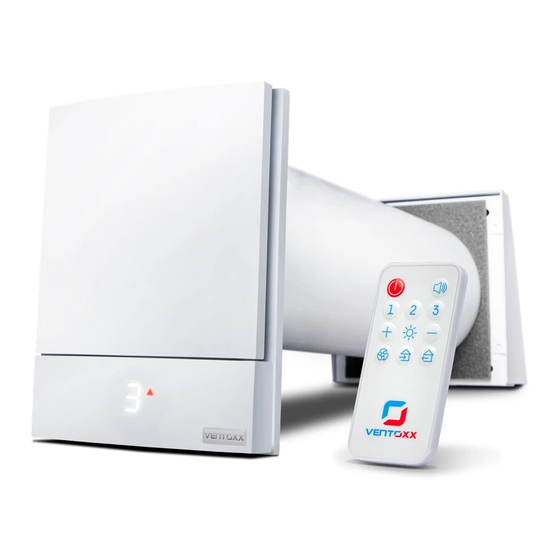
0.5 or 0.75 m in length as standard and is undercut according to the wall thickness before installation. 2.2. Complete set The Ventoxx Harmony consists of the following components: 1 - movable part of the inner cover 2 - a mounting plate with indication of current operating mode... -
Page 6: Technical Specifications Of The Ventoxx Harmony Hrv
12 - Ventoxx Twist control relay (as supplied) 13 - Ventoxx Twist control mounting plate (as supplied) 14 - box for installation of Ventoxx Twist control in the wall (as supplied) 15 - Ventoxx Twist control power supply unit (as supplied) Also included: ●... - Page 7 HRV capacity, m/h 17 to 50 Recovery efficiency, % 74 to 86 Noise level at a distance of 3 m, dB 12 to 22 Voltage, V 100-230 Power Consumption, W per hour 1.6 to 2.6 Type of heat exchanger the ceramic heat exchanger (Germany) Diameter of the hole in the wall, 160 to 180 Temperature mode of operation, °C...
-
Page 8: Preparing For Installation
3. Preparing for installation 3.1. Device placement Ventoxx Harmony HRV is stationary general exchange ventilation. Therefore, its overall performance and efficiency depend on the correct placement of the devices in the room, as well as the correct installation and use... -
Page 9: Safety During Operation
▪ Hearing protection ▪ Head protection ▪ Special work shoes. 4. Installation of the Ventoxx Harmony HRV 4.1. Making a hole in the wall To install the device, you must first make a round hole in the wall with the required diameter. -
Page 10: Step-By-Step Installation
4.2. Step-by-step installation Step 1: After selecting an installation location and making a mounting hole in the wall, run the 220 V power supply wire to it. Step 2: Measure the wall thickness, if you bought the set with the external metal cover, positions 8 and 9 in the picture of the complete set from the box, add another 15 mm to this value. - Page 11 The air duct must be placed in the wall so that the uncovered gap ("a" in the diagram) is at the bottom. Step 4: Insert the ceramic heat exchanger into the air duct and slide it in about half the length of the pipe.
- Page 12 Run the wires from the fan inside the room. Step 7a (optional): If your model is equipped with a Ventoxx Star sound attenuator, install it directly behind the fan in the free space between the fan cartridge and the edge of the air duct.
- Page 13 Step 8: To prevent precipitation from entering the wall material or insulation, the space between the hole in the wall and the air duct must be sealed on the outside of the building by applying a sealing mixture (plaster, mortar, or sealant). Step 9а: Attach an external grid if your set includes a back output diffuser grid to close the decentralized heat recovery unit from the street side.
- Page 14 duct of debris. Install the fasteners in the holes, attach the cover and bolt it to the wall with the fastening system. If the wall surface is rough or uneven, we recommend applying a sealant to the inside surface of the plastic grid flange to eliminate the gap between the cover and the wall.
- Page 15 On the part of the air duct that protrudes from the wall, put the mounting plate with sealant and make marks with a pencil for drilling holes. Remove the mounting plate. Drill the holes and remove debris from the holes and air duct. Please note, in case the wall reveals unevenness, it may cause precipitation entering and deterioration of the structure.
-
Page 16: The Electrical Connection Of The Device
- (Red) master device - (Blue) slave device The master device is the only device that responds to remote control or Ventoxx Twist control signals. On this device, the user can switch on the selected operating mode as well as switch the connected slave device to the desired operating mode. -
Page 17: Connection Of The Decentralized Heat Recovery Units To The Ventoxx Twist Control
5.3. Connection of the decentralized heat recovery units to the Ventoxx Twist control As a standard set, the Ventoxx Twist control has a power supply of 25 W and can be connected to 4 ventilation devices. To connect more devices, it is necessary to... -
Page 18: Wiring Schematics For Ventoxx Twist Fans And Controls
Please note that the Ventoxx Twist control and ventilation devices are not allowed to connect to a 230 V AC system. There is a high risk of injury due to electric shock! 5.3.1. Wiring schematics for Ventoxx Twist fans and controls The optimum choice of installation location is shown in the basic wiring diagram. -
Page 19: Installation Of The Ventoxx Twist Control In Wall
5.3.2. Installation of the Ventoxx Twist control in the wall Step 1: Make a hole in the wall with a diameter of 70 mm and a depth of 120 mm. If you do not want to install the power supply in the mounting box, you can remove the extension cord. -
Page 20: Completing The Installation And Commissioning
Step 4: Connect the power supply with 220 V to the power supply using a connection block. Then connect the 12 V power supply to the Twist control. Step 5: Install the control in the mounting box so that the regulator button moves clockwise. Press the faceplate down and lock it in place by applying slight pressure. - Page 21 Attention! Be careful not to damage the electronics compartment cover sealed with seals, damaging them will cause the device to be removed from the warranty. The two-wire cable with screw terminals (usually white or orange) is designed for a 220 V power supply. The power cable connected to the installation place of the device must be connected to the device cable by previously de-energizing the line for safety.
-
Page 22: Operation Of The Decentralized Heat Recovery Unit
In heat recovery mode, the ventilation device can operate at speeds from 1 to 3 for the remote control and from 1 to 5 for the Ventoxx Twist control. The choice of speed depends on the size of your room, the need for air exchange at a particular moment and your wishes regarding the intensity of ventilation. - Page 23 is operating in the exhaust phase and the blue arrow means that it is operating in the intake phase. If the decentralized heat recovery unit has been switched off in recovery mode, then after the power supply has been switched on again, the decentralized heat recovery unit resumes operation at the same speed that was selected before switching off.
-
Page 24: Automatic Ventilation In The Hot Season
7.3. Description of the indication symbols on the inner cover of the decentralized heat recovery unit The indication on the screen shows the operating mode selected by the user. The user can disable the display by remote control or Ventoxx Twist control - this in... -
Page 25: Control Of The Heat Recovery Unit With The Remote Control
no way affects the operation of devices. When switching the operating modes, the display briefly shows the selected mode and then fades out again. When off, the display is not visible at all on the inner cover of the decentralized heat recovery unit. -
Page 26: Control Of The Heat Recovery Unit With The Ventoxx Twist Control
Attention! In the complete set of the decentralized ventilation units with heat recovery with Ventoxx Twist control, there is no indication on the inner cover of the Ventoxx Harmony HRV! Indication on the Ventoxx Twist control and its meaning:... - Page 27 The bottom red LED on the left (off) A red LED that glows on the bottom left indicates that the ventilation devices are off, but the power is on. The bottom blue LED on the right (airing mode) The blue LED at the bottom right indicates that the decentralized heat recovery unit is in ventilation mode with no heat recovery.
-
Page 28: Device Maintenance
To activate the intensive airing mode, turn the device off by turning the relay counterclockwise. The red LED will light up, then press the button. The blue LED on the bottom left will light up and the decentralized heat recovery unit will start increasing the ventilation power. -
Page 29: Cleaning The Heat Exchanger And Other Components
Step 3: Remove the Ventoxx Star sound attenuator (if installed in the HRV) and fan cartridge from the air duct by pulling on the auxiliary cord. Remove the heat exchanger with the cord attached to it. -
Page 30: Troubleshooting Errors And Malfunctions
Connect the wires and place the movable part of the cover on the mounting plate. Connect the power supply. Watch "How to replace the filter and clean the heat exchanger in the Ventoxx decentralized heat recovery unit" video instructions: 8.3. -
Page 31: Quality And Warranty
Carefully read the installation and operation instructions of the Ventoxx ventilation device before installing and using it. The warranty period for any products by Ventoxx TM is 2 years from the date of purchase. The warranty on the heat exchanger is 10 years. - Page 32 In the event of a breakdown or malfunction during the post-warranty period, contact the distributor from whom the product was purchased. Official Ventoxx representatives check the correct operation of the device, troubleshoot and/or advise on the proper maintenance of the device.
Need help?
Do you have a question about the HARMONY and is the answer not in the manual?
Questions and answers