Table of Contents
Advertisement
Quick Links
Advertisement
Table of Contents

Related Manuals for Emulate Zoe-CM2

Summary of Contents for Emulate Zoe-CM2
- Page 1 Zoë-CM2 User Guide...
- Page 3 Zoë Culture Module ® Zoë means life. The Zoë-CM2 Culture Module is designed to sustain the life of cells within Organ-Chips. The instrument automates the precise conditions needed for simultaneous cell culture of up to 12 Organ-Chips. It supplies the dynamic flow of media and recreates the mechanical forces of breathing motions or peristalsis that help Organ-Chips recreate the microenvironment cells experience in the body.
- Page 4 Zoë Culture Module Table of Contents Introduction Specifications Safety Installation Page 7 Page 13 Page 17 Page 21 Introduction Zoë-CM2 Culture Module / Table of Contents...
- Page 5 Settings Updating Firmware & Care Help & Downloading Logs Support Page 29 Page 45 Page 49 Page 53 Page 55 Page 5...
- Page 7 Introduction This section provides an overview of Zoë and its functions. Equipment (what’s in the box) Zoë-CM2 Culture Module Chip Cradles Gas & Vacuum Supply Line Zoë Core Update Cable SensorPush HT1 Temperature and Humidity Smart Sensor Metal Spudger Pry Tool Ethernet Cable 24V Power Supply Page 7...
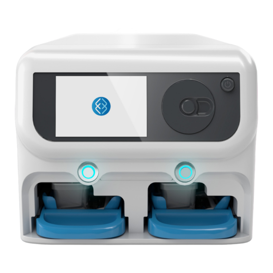
- Page 8 Zoë-CM2 Culture Module Power Button – Used to Components power the device on and off. Dial – Used for selecting 1. Zoë-CM2 Culture Module elements on the display, basic navigation, and adjusting 2. Power Button values. 3. Dial Dial Button – Used to confirm 4.
- Page 9 Organ-Chip Configuration 1. Bottom Channel Inlet Port 2. Top Channel Inlet Port 3. Vacuum Ports 4. Top Channel Indicator 5. Top Channel Outlet Port 6. Bottom Channel Outlet Port 7. Chip Body 8. Top Channel Indicator Page 9...
- Page 10 Configuration 1. Pod Reservoir Lid 2. Pod Reservoir 3. Organ-Chip 4. Chip Carrier Zoë-CM2 Culture Module / Introduction...
- Page 11 Components 1. Top Channel In 2. Top Channel Out 3. Vacuum Chamber 4. Bottom Channel Out 5. Bottom Channel In Page 11...
-
Page 13: Specifications
Specifications This section provides specific technical information and operational requirements. Included are system dimensions, thermal and gas requirements, and modes of operation. Page 13 Page 13... - Page 14 Gas Input Pressure: 276 kPa +/- 35 (40 psig +/- 5) Gas Input Composition: 5% CO , balance air Vacuum Input Pressure: -70 kPa (-10.2 psig) Manufacturer Emulate, Inc. 27 Drydock Avenue Environmental Operating Temperature: 20–38ºC (68-100. 4ºF) Boston, MA 02210 Relative Humidity: 0–90%...
-
Page 15: Operation
We take data privacy seriously. For more data from an instrument for information, please reference our Data Privacy streamlined support. & Security Policy for Emulate Software When a software update is Applications. available, Zoë can be updated over the air. - Page 17 Safety This section includes recommended precautions when handling and using Zoë-CM2. The information here describes how users can minimize the chance of harming themselves or the module during operation. Page 17 Page 17...
- Page 18 Zoë-CM2 Safety The Instructions Symbol The product is marked with this warning symbol where it is necessary for the user to refer to the instructions in the user guides. Regulatory Compliance and Testing This product has been tested to the requirements of: 61010-1 (IEC, EN, UL, CSA) IEC 61010-2-10 Safety Requirements for Electrical Equipment for measurement, control, and laboratory use...
-
Page 19: Caution Statements
Service and maintenance should only be completed by Emulate- Never attempt to maintain or sanitize Zoë without first disconnecting certified personnel. Never attempt to disassemble or repair Zoë... -
Page 21: Installation
Installation This section covers the basic installation of Zoë-CM2. Please reach out to Emulate Field Support for detailed installation guidance and support if needed prior to proceeding with installation. Ensure Orb and all hubs are connected before installing Zoë-CM2. Page 21... -
Page 22: Items For Installation
Zoë-CM2 Items for Installation Zoë-CM2 comes with the following items for installation: Power Cord Power Supply Zoë-CM2 Gas & Vacuum Ethernet Cable Supply Line Zoë-CM2 Culture Module / Installation... - Page 23 Zoë-CM2 Items for Installation The user will need to provide the following equipment for installation: Incubator 100% CO Gas Supply Orb-HM1 Note: Contact Emulate for guidance on user-provided equipment. Page 23...
-
Page 24: Installation Procedure
Zoë-CM2 Installation Procedure Preinstallation Setup Before commencing installation, ensure that incubators are fully operational. Unpack Zoë-CM2 with its accessories. Sanitize them with 70% ethanol prior to bringing them into the chosen operating environment. Make sure the box is not missing any accessories or parts (see page 7). Remove the SensorPush HT1 Temperature and Humidity Smart Sensor from the Zoë-CM2 box. - Page 25 Note: Zoë-CM2 and the SensorPush HT1 should be turned on and placed into the incubator for stabilization. Emulate recommends leaving them for four hours to enable accommodation of temperature and humidity settings. Open the SensorPush app and monitor the temperature over time.
- Page 26 Zoë-CM2 Installation Procedure Installation Run the Gas and Vacuum Supply Line through the incubator access hole. Plug the Power Supply into an APC UPS or grounded wall outlet, mount the Power Supply transformer to the back of the incubator, and run the Power Cord through the incubator access hole. Caution: Ensure the 24V Power Supply and Cord that came with Zoë-CM2 are being used.
-
Page 27: Connecting To A Network
Zoë-CM2 Installation Procedure Connecting to a Network Zoë-CM2 can be connected to the internet via the ethernet port on the back of Zoë. To connect to a wired network, plug the supplied Ethernet Cable into the network port on Zoë, and connect the other end to an active ethernet port. The system will connect automatically once an active connection is detected. - Page 29 This section describes proper interaction with, and operation of, Zoë-CM2. The instrument should always be used in an incubator while following aseptic procedures. Page 29 Page 29...
-
Page 30: Getting Started
Zoë-CM2 Getting Started Zoë-CM2 Interface Display Dial Dial button Bay Activation Buttons Power Button Powering On To power Zoë on, push the Power Button located on the upper-right corner of the faceplate. Zoë will then go through its startup routine until it displays the status screen. Zoë-CM2 Culture Module / Use... - Page 31 Zoë-CM2 Running the Prime Cycle The Prime Cycle perfuses media through the Pod before it is connected to a seeded chip to ensure no air is trapped when a chip is connected to the Pod. Prepare Pods per desired organ-specific protocol. Insert Tray with up to six Pods into a Zoë...
- Page 32 Zoë-CM2 Running the Prime Cycle (Continued) Press the Dial Button to select “Start,” which A status bar and timer will appear to show the will initiate the Prime Cycle. This will cause the progress of the Prime Cycle. manifolds to lower. Zoë-CM2 Culture Module / Use...
- Page 33 Zoë-CM2 Once the Prime Cycle is complete, the status bar Remove the primed Pods from Zoë and attach the and timer will disappear, the manifolds will rise, prepared chips to the Pods. Reference organ- and the Bay(s) will be deactivated. specific protocols for instructions on chip preparation prior to attachment.
- Page 34 Zoë-CM2 Press the Dial Button to edit the “Media” type. Rotate the Dial to select between Fluid and Air/Gel: Selecting Media Type Using the Dial, hover over the areas below “Media” denoting the “Top” and “Bottom” channels. Zoë-CM2 Culture Module / Use...
- Page 35 Zoë-CM2 Selecting Media Type (Continued) These settings will now take effect on Zoë. After hovering over the desired media type, press the Dial Button to confirm. Note: If selecting Air/Gel, the flow rate will automatically be set to 0 to prevent media flow, as there is no flow in the channel when “Air/Gel”...
- Page 36 Zoë-CM2 Press the Dial Button to begin editing flow rate. Rotate the Dial to adjust the flow rate between 10 and 1,000 μL / hr. Programming Flow Rate Using the Dial, hover over the areas below “Rate” denoting the “Top” and “Bottom” channels. Zoë-CM2 Culture Module / Use...
- Page 37 Zoë-CM2 Programming Flow Rate (Continued) After rotating to the desired flow rate, press the These settings will now take effect on Zoë. Dial Button to confirm. Page 37...
- Page 38 Zoë-CM2 Press the Dial Button to begin editing the strain. Rotate the Dial to adjust the level of strain between 0% and 12%. Programming Stretch Parameters Using the Dial, hover over the “Strain” parameter. This option allows you to set the amount of stretch on the chips.
- Page 39 Zoë-CM2 Programming Stretch Parameters (Continued) After reaching the desired level of strain, Using the Dial, hover over the “Frequency” press the Dial Button to confirm. parameter. This option allows you to set the frequency of stretch. Page 39...
- Page 40 Zoë-CM2 Programming Stretch Parameters (Continued) Press the Dial Button to begin editing the frequency. After reaching the desired frequency, press the Dial Rotate the Dial to adjust the frequency between Button to confirm. 0.00 and 0.40 Hz. Zoë-CM2 Culture Module / Use...
- Page 41 Zoë-CM2 Running Regulate™ Cycle The Regulate Cycle is designed to remove any microbubbles Using the Dial, hover over “Regulate Cycle” on the that may have been introduced during the activation and display. Press the Dial Button to select. seeding steps. Note: If modeling ALI or filling the top/bottom channel with gel, be sure to select “Air/Gel”...
- Page 42 Zoë-CM2 A status bar and timer will appear and show progress of the Regulate Cycle. Running Regulate™ Cycle (Continued) Rotate the Dial to bring up the “Start” option. Press the Dial Button to select “Start,” initiating the Regulate Cycle. To cancel the Regulate Cycle, rotate the Dial to bring up the “Cancel”...
-
Page 43: Shutting Down
Zoë-CM2 Running Regulate™ Cycle (Continued) Once the Regulate Cycle is complete, the status bar and timer will disappear, and the system will revert to the preset flow and stretch parameters. Shutting Down Press the Power Button on the front of Zoë. Page 43... - Page 45 Settings Page 45 Page 45...
-
Page 46: System Information
Zoë-CM2 Settings System Information The “System Information” screen provides details on Zoë Model, Name (ID), Serial Number, Software Version, and Hardware ID. This screen can be accessed by hovering over To close the “System Information” screen, hover and selecting the icon on the lower right of the screen. -
Page 47: Network Connection
Zoë-CM2 Settings Network Connection To check the status of the network connection, use the If there is an active ethernet connection, “Connected” will Dial to hover over the “Ethernet” icon in the top bar of the automatically be displayed along with the IP address. If display. - Page 49 Updating Firmware & Downloading Logs Page 49 Page 49...
- Page 50 Zoë-CM2 Updating Firmware & Downloading Logs Updating Zoë Firmware To update the Zoë firmware, download the “Utility Hub” application from emulatebio.com/utility-hub. The application is compatible with computers running Windows 7 or a later version. Follow the instructions displayed on Utility Once Utility Hub has been downloaded, open the Hub to update the Zoë...
-
Page 51: Downloading Logs
Zoë-CM2 Updating Firmware & Downloading Logs Downloading Logs Open Utility Hub and select “Download Logs”. Follow the instructions displayed on Utility Hub to download the logs from Zoë-CM2. Page 51... -
Page 53: Help And Support
Help & Support Contact Emulate Support for any issues with Zoë-CM2. Email: support@emulatebio.com Website: https://emulatebio.com/contact-support/ Phone: +1 844-902-4477 (Toll Free) +1 781-583-3515 Page 53 Page 53... - Page 55 Care Page 55 Page 55...
-
Page 56: Cleaning And Maintenance
Care Cleaning & Maintenance Care for Zoë includes periodic cleaning. Preventative maintenance should be performed by a qualified Emulate Field Engineer at least once per year. Contact Emulate Support for additional details and to request an appointment. Regular checks and recordkeeping provide helpful information should any troubleshooting be required. -
Page 57: Troubleshooting
There is an unknown internal error with Zoë. Contact Emulate for troubleshooting. The Power Cord is damaged. Replace Power Cord; contact Emulate for replacement. Bay is empty or Tray is not fully inserted into the Bay. Insert Tray until the Tray snaps into place. - Page 58 Copyright 2021 Emulate, Inc. User Guide EP-210 Rev A All rights reserved For Terms and Conditions and Legal Notices refer to our website at: emulatebio.com/legal...
Need help?
Do you have a question about the Zoe-CM2 and is the answer not in the manual?
Questions and answers