
Related Manuals for MedaCure LX-BARI-SF

Summary of Contents for MedaCure LX-BARI-SF
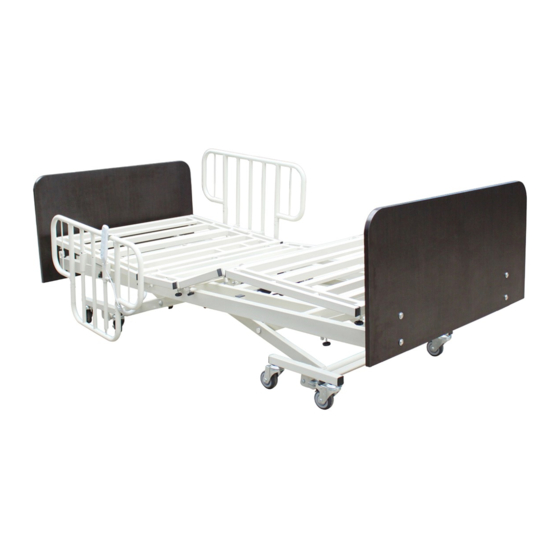
- Page 1 B AR I AT R I C B E D - S P L I T F R AM E 5 FUNCTION ELECTRIC BED EXPNADABLE WIDTH FROM 36” – 42” – 48” MODEL # LX-BARI-SF © 2018 MADE IN CHINA...
-
Page 2: Table Of Contents
TABLE OF CONTENTS PAGE 2 INRODUCTION AND PRODUCT FEATURES PAGE 3 PARTS LIST AND DESCRIPTION PAGE 4 INSTALLING THE MIDDLE FRAME PAGE 5 INSTALLING THE LIFTING FRAME PAGE 5 - 6 INSTALLING MOTORS AND MOTOR CONNECTING WIRES PAGE 6 - 7 INSTALLING THE LENGTH EXTENSION FRAME PAGE 7 - 9 INSTALLING BED BOARDS... - Page 3 The MedaCure Lincoln Expandable Bed is a fully electric, versatile and multi-functional bed for Long Term Care, Hospital & Home Care settings. It expands in both the width (from 36” to 48”) and length (from 80” to 88”) which makes it ideal for standard, bariatric and tall patients. It has a low position of 14.9” and 5 patient position functions to enhance the quality of care and for ultimate comfort.
-
Page 4: Parts List And Description
PARTS LIST & DESCRIPTION IMPORTANT: Read this manual completely before setting up or operating this system and keep in a safe place for future reference. To avoid injury and for maximum safety, this system should only be installed by an authorized technician or dealer representative. Electric bed installation parts listed below as per Figure # 1 Bed head frame Bed foot frame... - Page 5 1. Installing the bed frame 1.1 Installing the bed frame junction block Screw off M10 bolt, Insert the junction block (the end with threaded hole) into the rectangular tube of the bed head frame, matching the bolt hole and fasten by M10 bolt with φ10 spring washer & φ10 flat washer.
-
Page 6: Installing The Lifting Frame
2. Installing the lifting frame Remove the φ13.5 bolt from the lifting frame (1). Place a φ14 plastic washer between the lifting frame (1) and lifting frame (2), matching the bolt holes on both lifting frames. Fasten with a φ13.5 bolt with cotter pin as per Figure # 4. -
Page 7: Installing The Length Extension Frame
Motor B connecting wire for the Hi/Lo function in the bed head frame Motor C connecting wire for foot position Backup battery connecting wire Motor D connecting wire for Hi/Lo function in the bed foot frame Backup battery Motor A connecting (OPTIONAL) wire for head section Remote Control connecting wire... - Page 8 4.2. Install the bracket for bed foot part as per Figure # 8. Figure # 8 5. Installing the bed boards 5.1 Press the M8 × 18 plate nut into the bed board holes, as per Figure # 9. Figure # 9 5.2.1 Match the bed head board with the bed frame installation holes.
- Page 9 5.2.2 Foldable bed head board installation as noted in Figure # 11 Unfolded Status Folded Status Figure # 11 P a g e...
- Page 10 5.3 Match the bed foot board with the extension frame installation holes. Fasten by M8 X 20 cup head bolt with φ 8 flat washer. Bed foot board can be installed in both the high and low level position. See Figure # 12 & Figure # Figure # 12 Bed foot board in low-level installation position Figure # 13 Bed foot board in high-level installation position 5.4 Install the bed head board to the bed head frame, and bed foot board to the bed foot frame,...
-
Page 11: Casters
6. Casters There are 4 pcs. locking casters and 4 pcs. swivel casters per set. Step on the locking pedal (lower) to activate the locking position and step on the unlocking pedal (upper) to deactivate the locking system. See Figure # 15 & 16. Step on the pedal to lock Step on the pedal to the caster in place... - Page 12 7.2 IMPORTANT NOTE: There are 3 location holes on each extension frame for 3 width adjustment settings - 36”, 42” and 48” widths. There are 4 separate extension frames on each side of the main frame. Repeat the above method in 7.1 to achieve the desired width and then tighten the “Locking Bolt”...
-
Page 13: Bumper Guard Installation And Usage
9. Each corner of the bed frame has two mattress retainer installation holes. Insert the mattress retainer as noted in Figure # 20. Mattress Retainer Installation for Standard Bed Deck Mattress Retainer Installation for Expandable Bed Deck Figure # 20 Bumper Guard Installation and Usage There are two retractable rubber Bumper Guards on the head of the bed. - Page 14 10.2 Extended Position: Push the bumper guard stem upward and turn the stem outward until the screw clicks with slot as noted in Figure # 22. Figure # 22 10.3 Retracted Position: when bumper guard is not in use, push the stem upward and turn it inward until screw clicks with slot as noted in Figure # 23 Figure # 23 11.
-
Page 15: Patient Remote Control
11.2 To raise the side rails - Pull up until the rail clicks in place. To lower the side rails - release the pulling button as per Figure # 25. Figure # 25 12. Patient remote control First ensure the power wire is connected. Patient can easily control the bed positions by using the patient remote control, including adjusting the bed height, raising and lowering the back head and foot sections, trendelenburg and reverse trendelenburg. -
Page 16: Battery Backup
Figure # 27 Trendelenburg position Figure # 28 Reverse Trendelenburg position 13. BATTERY BACKUP (OPTIONAL – NOT AVAILABLE ON ALL MODELS) Install the backup battery onto the control box rack, screw in and connect the wires (See figure # 6 in section 3.2 of this manual) The optional emergency battery backup enables the caregiver to control all functions with the patient remote control in case of a power outage or during patient transport.
Need help?
Do you have a question about the LX-BARI-SF and is the answer not in the manual?
Questions and answers