
Related Manuals for matev MOW-H 160 CM


Summary of Contents for matev MOW-H 160 CM
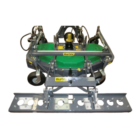
- Page 1 GmbH Nürnberger Str. 50 90579 Langenzenn, Germany T +49 9101 9087 -0 F +49 9101 9087 -20 info@matev.eu www.matev.eu Original Operating Manual MOW-H/M 160 CM Combination Mower Version 09/2017...
-
Page 2: Table Of Contents
Contents Table of contents About this operating manual ........................3 Safety ................................. 4 Intended use ............................... 4 Qualifications of personnel ......................... 4 General safety notices ..........................5 Special safety notices ..........................5 Basic rules ..............................7 Task and use ............................. 8 Task ................................ -
Page 3: About This Operating Manual
About this operating manual About this operating manual Dear customer! Dear customer! Thank you for purchasing this implement, we appreciate your trust. Prior to using this implement for the first time, read this operating manual carefully and conscientiously all the way through. Keep this operating manual where it is easily accessible. -
Page 4: Safety
Safety Safety Note! Must be read. Guidelines and instructions that you must comply with are presented in this section. Persons who install, operate and maintain the mower must have read and understood this operating manual. Intended use The mower is designed for municipal tractors or carrier vehicles with the following power ratings: ... -
Page 5: General Safety Notices
Safety General safety notices General safety notices are explained in this section. These safety notices are used in the subsequent sections. In addition to the safety aspect, you will save money and work time if you comply with these notices. Comply with these safety notices to ensure safe operation and to save work time and costs. - Page 6 Safety Attention! Prior to performing maintenance and repair tasks, turn off the engine and remove the key! Attention! Prior to commissioning, read and comply with the operating manual and safety notices! Attention! Injuries due to fluid escaping under high pressure. Comply with the notice in the operating manual.
-
Page 7: Basic Rules
Safety Attention! Implement is only suitable for a PTO shaft speed of 2000 rpm! Attention! Implement is only suitable for a PTO shaft speed of 1000 rpm! Attention! Implement is only suitable for clockwise PTO shaft rotation! Attention! Implement is only suitable for counterclockwise PTO shaft rotation! Attention! Do not allow the mower to run without discharge guard or suction port! Lubricating point... -
Page 8: Task And Use
Task and use Task and use Task The mower is used for mowing green areas. The area of application extends from mani- cured lawns, to matted grass to uncultivated land. Function The mower works with three rotating blades, these blades are powered by the tractor via the working hydraulics. -
Page 9: Mowing Irregular Areas
Task and use 3.3.2 Mowing irregular areas Fig. 2: Irregular area Divide irregular areas into smaller sections. Change the mowing pattern frequently; do not always work in the same pattern. 3.3.3 Mowing large areas Fig. 3: Large area Mow large free areas as shown on Fig. 3. 3.3.4 Mowing small areas Fig. -
Page 10: Delivery And Transport
Delivery and transport Delivery and transport The mower is delivered lashed on a pallet. Lifting the mower off of the pallet Remove the protective packaging and the transport safeguard. Lift the mower off of the pallet with a suitable device (crane or forklift) and set it down. -
Page 11: Mounting The Front Mower On The Carrier Vehicle
Mounting the implement Mounting the front mower on the carrier vehicle Fig. 5: Mounting the mower on the carrier vehicle The following optional attachment possibilities are available for the mower: Attachment – cat. 0 Cat 1 attachment Attachment –... - Page 12 Mounting the implement Depending on tractor type the supplied universal joint shaft may be too long. Carry out the steps described below to shorten the PTO shaft. 1. Mount the mower on the tractor 2. Pull the two halves of the universal joint shaft apart 3.
-
Page 13: Mounting The Universal Joint Shaft
Mounting the implement 8. Repeat steps 6 to 8 on the other half of the universal joint shaft. 9. Grease the profile tubes (see Fig. 9). Fig. 9: Grease the profile tubes 10. Slide the profile tubes together. 5.2.1 Mounting the universal joint shaft 1. -
Page 14: Mowers With Hydraulic Drive
Mounting the implement Mowers with hydraulic drive 1. Connect the 3 hydraulic hoses (flow, return, and leak oil line) to the vehicle. 2. Place the front hydraulics in float position. 3. Switch the mower on briefly. 4. Check the direction of rotation of the blades. The blades must rotate clockwise (as viewed from above). -
Page 15: Operation
Operation If you use the side discharge without suction port, you must mount the rock impact guard on the mower, secure it with the stop nuts and swing it down. Do not use the side discharge without rock impact guard. Rock impact guard... -
Page 16: Securing The Mower For Road Travel
Operation Securing the mower for road travel For longer road travel to the implementation site the mower can be safeguarded against oscillation. There are two possibilities for this; via the shut-off valves and via the locking pin. The safeguard must be removed for mowing! 6.1.1 Via shut-off valves (Only included for the option: Lift-out in maintenance position) -
Page 17: Via Locking Pin
Operation 6.1.2 Via locking pin The mower deck can also be secured via the depicted locking pin. Fig. 15: Locking pin Adjusting the cutting height on the rigid frame Attention! Adjust the four wheels uniformly. Fig. 16: Caster on the rotary mower 1. -
Page 18: Adjusting The Cutting Height On The Hydraulic Frame
Operation Adjusting the cutting height on the hydraulic frame Caution – moving parts. Prior to changing the cutting height, ensure that no one is on the mower. The mower can be adjusted in height via the hydraulic cylinder. Fig. 17: Hydr. height adjustment Fig. -
Page 19: Swing Up The Mower Into Maintenance Position And Swing It Back Down
Operation Swing up the mower into maintenance position and swing it back down Do not switch on the mower in maintenance position. Switch off the engine and remove the ignition key, after the mower has been brought into mainte- nance position. - Page 20 Operation 4. Swing up the mower hydraulically Fig. 21: Mower in maintenance position 5. Place the shut-off valves in position for "Securing in maintenance position". Fig. 22: Position of the shut-off valves 6. Executing maintenance tasks After maintenance tasks 7. Place the shut-off valves in position "Turning into maintenance position". 8.
-
Page 21: Lawn Harrow
Operation Lawn harrow Fig. 23: Lawn harrow Beware of moving parts. Prior to lifting out or lowering the lawn harrow en- sure that no one is on the mower. Ensure that the safety bolt is always mounted in the working position as shown in Fig. -
Page 22: Changing The Plunge Depth Of The Tines
Operation 6.5.1 Changing the plunge depth of the tines The harrow must be adapted to the respective cutting height for an optimal plunge depth of the tines. This is achieved with the aid of the stroke limitation when retracting the cylin- der. -
Page 23: Move Lawn Harrow To Transport Position
Operation 6.5.2 Move lawn harrow to transport position 1. Completely lift out the lawn harrow. 2. Remove the safety bolt from Fig. 24 3. Now drag the rake further back as shown in the Fig. below Fig. 26: Transport position of the rake 4. -
Page 24: Changing The Inclination Angle Of The Tines
Operation Fig. 27: Safety bolt in transport position 5. Take the previously removed safety bolt and slide it into the holes that are now in line. 6. Repeat this on the other side as shown in the Fig. below. Second safety bolt in transport position Second safety bolt in work position... - Page 25 Operation Fig. 29: Angle adjustment Adjusting the air supply For a clean grass flow it is important that sufficient air can flow into the mower. The intake air is accelerated through the mower discharge together with the cut grass. This is the on- ly way to exclude the possibility of clogs in the mower or in the suction port.
-
Page 26: Maintenance
Maintenance Maintenance General information Attention! Personal injury or damage to the tractor and the implements can occur. Before each use of the implements check all safety-relevant parts and the hydraulic connections. Danger! Only perform service and maintenance tasks when the tractor is ... -
Page 27: Maintenance Schedule
Maintenance 7.2.1 Maintenance schedule Daily service: Prior to each use, check the safety elements and moving parts for wear Check the hydraulic connections and lines Trial run before each use The entire implement must be cleaned after each use ... -
Page 28: Lubricating Schedule
Maintenance 7.2.4 Lubricating schedule At regular intervals (every 50 operating hours) and always at the beginning and end of the season, the moving parts of the implement must be greased or oiled. Grease the marked points with a grease gun as specified in the lubrication schedule. 1. - Page 29 Maintenance Fig. 34: Upper lubrication points of the lawn harrow Fig. 35: Lower lubrication points of the lawn harrow Page 29...
-
Page 30: Adjusting The Mower Deck
Maintenance 7.2.5 Adjusting the mower deck If the mower deck is not correctly adjusted and thus a diagonal mowing pattern occurs, align the mower again via: 1. The four suspension points 2. The two upper links (only with hydraulic height adjustment) Fig. -
Page 31: Tire Pressure
The implements must be disposed of in accordance with the applicable regulations of the municipality or the country. Take the parts to the collection points for residual waste, special waste, or recycle them depending on material. matev GmbH does not provide any disposal services. Page 31... -
Page 32: Guarantee
Guarantee Guarantee The General Terms & Conditions of matev GmbH provide information on the guarantee conditions. matev GmbH Nürnberger Str. 50 90579 Langenzenn, Germany Technical data and accessories Width 1616 mm Height 650 mm Depth (without lawn harrow) 1446 mm... -
Page 33: List Of Illustrations
List of illustrations Fig. 1: Clean the work terrain ........................8 Fig. 2: Irregular area ............................9 Fig. 3: Large area ............................9 Fig. 4: Small area ............................9 Fig. 5: Mounting the mower on the carrier vehicle ..................11 Fig. -
Page 34: Eg - Declaration Of Conformity
EG – Declaration of Conformity EC Declaration of Conformity for a machine to confirm compliance with Directive 2004/42/EC and with the statutory regulations issued for its implementation. The manufacturer matev GmbH Nuremberg Str.50 90579 Langenzenn, Germany declares that the machine...
Need help?
Do you have a question about the MOW-H 160 CM and is the answer not in the manual?
Questions and answers