
Summary of Contents for ECKELMANN E-Control CNC
- Page 1 PRODUCT DOCUMENTATION E-Control Introduction Manual ENC66 eckelmann.de ECKELMANN AG, WIESBADEN • eckelmann.de • FERROCONTROL GMBH & CO. KG, HERFORD...
- Page 2 Eckelmann AG Berliner Straße 161 65205 Wiesbaden +49 (0) 611 / 7103 - 0 +49 (0) 611 / 7103 - 133 E-Mail info@eckelmann.de Internet http://www.eckelmann.de...
- Page 3 Content of this document: Additionally to the CNC task the E·Control ENC66 controller can run a PLC program. The manual is designed to generate a simple CNC program with the Eckelmann controller E•ENC where particular previous knowledge of CNC programming is not required.
- Page 4 Revision notification Tabelle 1: Tabelle 2: Tabelle 3: Version Chapter Date edited by Amendment 23.09.2010 Martin Kellner First release based on the introduc- tion manual of the ENC55 1.4.6.2 29.03.2011 Martin Kellner - E108 and F703 added - Data blocks corrected for diagnostic address of the LBM modules 4 / 97...
-
Page 5: Table Of Contents
Introduction Manual ENC66 Table of Contents Overview................12 List of documents....................12 Controller family E-CONTROL CNC ..............13 Variants „Stand-Alone“ and „With PC-HMI“............. 14 Status information of the ExC66................. 15 1.4.1 Status information during booting ..............15 1.4.2 LEDs while booting ....................16 1.4.3... - Page 6 4.2.5 MAC address ......................38 Update of the firmware via the boot monitor ....39 Access to the boot monitor ................. 39 Check of the firmware version................40 5.2.1 Variant „with PC-HMI“ ..................40 5.2.2 Variant „Stand-Alone“ ..................40 Update of the firmware ..................40 Remove a firmware .....................
- Page 7 10.11.5 Stopping of the program in the controller ............88 10.11.6 Reset of the data memory in the controller............88 10.11.7 Permanent storage of the program in the controller (boot-project) ....88 10.11.8 Termination of communication with the controller.......... 89 eckelmann.de 7 / 97...
- Page 8 Testing of the CNC and PLC program ......... 90 11.1 Connection of the controller inputs ..............90 11.2 Loading and starting the PLC program .............. 90 11.3 Loading and starting of the CNC program ............90 11.4 Error messages of the CNC program ..............91 8 / 97...
- Page 9 2. A blue bar with the word „Note“ 3. The text of the note below the bar Example: Note Please observe that the extended interface generates a bus load, which is higher by approx. 50 %. eckelmann.de 9 / 97...
-
Page 10: Warning Levels
Explanations regarding the safety instructions Safety instructions and hazard warnings are composed of five parts: 1. An icon at the margin 2. A bar with the signal word, the colour of which depends on the danger level. 3. A short, clear description of the danger 4. -
Page 11: Warning Signs
ESD (elec- trostatic discharge), overload or wrong connection. Warning of mechanical Nonobservance of the warning may damage or damage to the machine even destroy machine parts. Table 2: Warning signs eckelmann.de 11 / 97... -
Page 12: Overview
Overview List of documents The manual makes reference to other documents that include the respective details. Tabelle 3: Manual User manual PLC/2 for CNC Installation manual Standard HMI User manual Standard HMI Communication protocols different technical manuals for FBM modules Diverse ECNC configuration manual ECNC programming instruction manual ECNC configurations instructions ... -
Page 13: Controller Family E-Control Cnc
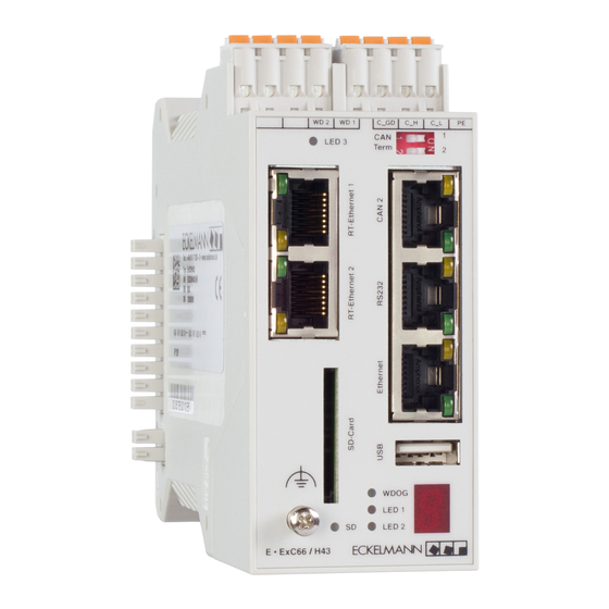
Introduction Manual ENC66 Controller family ECONTROL CNC Abbildung 1: The controller family E-Control CNC comprises the ENC66, ENC55, PNC55 and CNC55 controllers. This manual describes the ENC66 controller, that is designed for top hat rail mounting. The memory size and the number of interfaces depends on the or- dered configuration. -
Page 14: Variants „Stand-Alone" And „With Pc-Hmi
Variants „Stand-Alone“ and „With PC-HMI“ On principle, the controllers can be operated in 2 different operating modes: • The variant „Stand-Alone“ starts with the firmware immediately after the application of the voltage • The variant „With PC-HMI“ waits after the application of the voltage for the loading of a firmware from a PC via the program StdHMI The variant „With PC-HMI“... -
Page 15: Status Information Of The Exc66
Tabelle 7: 7-segment indicator Meaning Hardware initialization RAM test Initialization terminated Loading of firmware from FROM to RAM Firmware loaded Firmware started Table 7: 7-segment indicator, Status information during booting eckelmann.de 15 / 97... -
Page 16: Leds While Booting
1.4.2 LEDs while booting The single LED on the front panel indicate the following state and meaning during boot- ing. Tabelle 8: Indication Meaning WDOG Watchdog is not triggered in bootloader CAN1/LED1 Not used CAN1/LED2 Not used CAN2/yellow Not used CAN2/green Not used RS232/green... -
Page 17: Status Information During Start Of Firmware
Hardware check Flashing light of segment Normal state acc. to description in /A/ Continuous error number Error state acc. to tables in chapter 1.4.6.1 Table 9: 7-segment indicator, Status information during start of the firmware, ENC66 eckelmann.de 17 / 97... -
Page 18: Status Information In Normal Operation
1.4.4 Status information in normal operation After the start of the firmware, the controller changes to normal operation. The single segments of the 7-segment indicator are assigned to a system task each. The brightness of the various segments corresponds to the computing load of the single tasks in the system. -
Page 19: The Leds In Normal Operation
RX or TX ETHERNET/green Off: no ethernet connection available as soon as an ethernet connection is estab- lished (result of the internal link integrity test) Table 11: LEDs in normal operation, ENC66 eckelmann.de 19 / 97... -
Page 20: Error Indication
1.4.6 Error indication 1.4.6.1 Error indication during booting Probable errors in the booting phase are signalled by the following indication pattern. The indication shows the pattern sequentially with 2 characters/sec. The indication is made until the controller is reset (exception: start of the boot monitor). Tabelle 12: 7-segment indicator Meaning... - Page 21 UTI / Battery for CMOS and RTC buffering running out (warning repeated in 10- sec. interval) E88xx- Processor exception xx (hex) to address yyyyyyyy (hex) at stackpointer zzzzzzzz yyyyyyyy- (hex) zzzzzzzz Table 13: Error indication in normal operation, ENC66 Meaning: F...: Fatal E...: Error H…: Note eckelmann.de 21 / 97...
-
Page 22: Connection And Installation
Connection and installation Example of a structure Abbildung 3: Watchdog FBM modules E-DARC E-Motors E-Control ExC66 with power supply and LBM IO modules CAN1 WD 2 WD 1 C_ GD C _ H C _ L 24 V 24 V 24 V 24 V 24 V... -
Page 23: Type Of Connections Between Controller And Pc
PC to the network (RJ45) Table 14: Type of connections between controller and PC Note Connecting to a controller with a terminal program can be done via the serial port or eth- ernet. eckelmann.de 23 / 97... -
Page 24: Serial Connection
Abbildung 6: Local connection via Serial connection Network ethernet WD 2 WD 1 C_ GD WD 2 WD 1 C_GD WD 2 WD 1 C_GD Term Term Term WDOG WDOG WDOG LED1 LED1 LED1 LED2 LED2 LED2 ExC66 ExC66 ExC66 Figure 6: Connection controller <-->... -
Page 25: Connection Via Ethernet (Local Connection)
An Ethernet crossover patch cable STP Cat5 is required for a local connection between the controller and the PC. Connection via Ethernet 2.4.2 (network) An Ethernet crossover patch cable STP Cat5 is required for a connection between the con- troller and the PC via the network. eckelmann.de 25 / 97... -
Page 26: Monitor Interface Of The Controller
Monitor interface of the controller The ENC has an extended monitor interface with Z-modem file transfer via the serial RS232 interface. The monitor interface is available at the CPU at plug X3. By means of this interface • Commands of the monitor program of the ENC can be used •... - Page 27 Number of Data bits Parity Stop bits Flow control Table 15: connection parameters The dialog box looks like this: Abbildung 10: Figure 10: Dialog box with connection parameters After the parameterization the terminal window opens as follows: eckelmann.de 27 / 97...
-
Page 28: Calling Of The Monitor Interface
Abbildung 11: Figure 11: Terminal window Calling of the monitor interface With operating controller firmware (Watchdog LED is on), the monitor interface is activat- ed by the input of a question mark '?', recognizable by the input prompt '>'. The following steps are necessary to reach the monitor interface: •... - Page 29 Introduction Manual ENC66 Abbildung 13:. Figure 13: Prompt of monitor interface • Monitor interface is active eckelmann.de 29 / 97...
-
Page 30: Configuration Of An Ethernet Connection
Configuration of an Ethernet connection The ENC66 controller also makes it possible to connect to the monitor interface via ether- net. This connection uses the telnet protocol and can be established with a terminal pro- gram. In the example the Hyperterminal program is used. After starting the program type a name for the connection (e.g. - Page 31 Note A Firmware update can only be done via the serial interface. The Ethernet interface can‘t be used for this purpose. (For further information see chapter 5, „Update of the firmware via the boot monitor“). eckelmann.de 31 / 97...
-
Page 32: Important Monitor Commands
Important monitor commands Tabelle 16: Command meaning dir [dr:][pattern] Displays the table of contents of the indicated device. The flash disk (sd:) is preset, other possible devices are program memories (ps:), Ram disk (rd:), SD card(SC:), mass storage device at the usb port(MS:) and floppy disk (fd:) if available. -
Page 33: Possible Errors
(due to the bridge, the characters are transmitted back in the form of an echo), the cable is to be checked for a mixed up pin assignment (Pin2/3), for a short circuit and the connection is to be checked for correct parameters. eckelmann.de 33 / 97... -
Page 34: Setting Of The Ip Address In The Controller
Setting of the IP address in the controller The IP address is required if the controller is connected with the PC via a network or a local Ethernet cable. At delivery, the controller has a specified but optional IP address (with subnet mask). More- over, it has a specified unchangeable MAC address. -
Page 35: Setting Of The Ip Address Via Ethernet (Network Or Local) With Netconf
The controller uses its stored IP address until it is changed. Note The Eckelmann controllers accept only addresses that are assigned by the program NetConf in order to avoid possible conflicts with other BootP or DHCP servers. The configurations of other DHCP and BootP servers are ignored. -
Page 36: Change The Ip Address Of A Controller With Netconf
Abbildung 20: Figure 20: NetConf displaying controllers in the network 4.2.2 Change the IP address of a controller with NetConf Existing entries in the controller list can be modified in the following way: • The IP address of a selected controller can be modified with the menu entry „Edit-> Edit Item“. -
Page 37: Configure Gateway And Subnet Mask In Netconf
Additionally a controller can be configured without an existing entry in the controller list. The following steps have to be performed: • With the menu entry „Edit->New Item“ you add a controller to the list. The fields for MAC- and IP- Address are empty in the beginning. eckelmann.de 37 / 97... -
Page 38: Mac Address
This address can be used for an addressing on the hardware level. The address has a fixed length of 6 bytes (48 bit) and includes an address type, an identification of the manufactur- er and a serial number. Addresses of the ECKELMANN AG: 00:05:7E:xx:xx:xx. 38 / 97... -
Page 39: Update Of The Firmware Via The Boot Monitor
• Two adjacent segments of the 7-segment display rotate in clockwise direction Note The resetting of the controller can be made with running firmware by the input of 'reboot' in the monitor interface or by switching on/off of the controller. eckelmann.de 39 / 97... -
Page 40: Check Of The Firmware Version
Check of the firmware version The version of the firmware can be checked with the command „ver“ as soon as the prompt „>“ of the bootmonitor is displayed. 5.2.1 Variant „with PC-HMI“ If there is no firmware installed, only the version of the boot loader is displayed. The net- boot functionality is already part of the boot loader that is used with the ENC66. - Page 41 • The loading procedure takes several seconds. Two adjacent segments rotate in clock- wise direction on the 7-segment display. • The following messages are displayed, if the file ENC66.rsc is transferred as a firmware to be used for the stand-alone operation: eckelmann.de 41 / 97...
-
Page 42: Remove A Firmware
Abbildung 32: Figure 32: Transfer of the CNC firmware finished The controller reboots after the input of „quit“. The green WATCHDOG LED is on af- ter the start of the new firmware. The terminal program an be closed. Remove a firmware If a ENC66 is in the stand alone mode, the firmware has to be removed first to be able to use the controller with the StdHMI. -
Page 43: Commands Of The Boot Monitor
Removes the controller firmware. The bootloader stays on the controller and provides the netboot functionality to transfer the firmware from the StdHMI to the controller. The controller doesn‘t work stand-alone anymore. Table 18: Boot monitor commands eckelmann.de 43 / 97... -
Page 44: Parameterizing Of The Drives
Parameterizing of the drives The drives characteristics have to be parameterized in the drive itself but also in the con- troller. Machine constants are required to parameterize the drive in the controller. A ma- chine constant MK is composed of a key word and the respective values (for further details please check /6/). -
Page 45: Important Machine Constants
X,Y, Z, C, U, V, W, A, B, u, v, w, x, y, z, a, b, c -1 = no axis number is assigned to the axis denomination 0..15 = an axis number is assigned to the axis denomination Table 19: Important machine constants eckelmann.de 45 / 97... -
Page 46: Important Machine Constants
MK key word numb Values Meaning er val- MK_ACHSENART Assigning of the type of axis to the axis number in the order of the axis number 0..15 Bit 0 Axis of rotation xxxxxxxxxxx0 Linear axis xxxxxxxxxxx1 Axis of rotation Bit 1 Limit switch xxxxxxxxxx0x consider HW limit switch xxxxxxxxxx1x... - Page 47 [ms] in the order of the axis number 0..15 MK_VBAHNMAX Max. path speed [m/min] MK_BAHNBESCHL Acceleration ramp [m/sec^2] MK_BAHNBREMS Brake ramp [m/sec^2] MK_T_BAHNBESCHL Damping time constant for brake and acceleration ramps [ms] Table 19: Important machine constants eckelmann.de 47 / 97...
-
Page 48: Machine Constants File
Machine constants file The machine constants file is loaded into the controller during the start-up of the StdHMI. The following example of machine constants for 16 axes is a section of the file with preset machine constants that are to be adapted for the specific case of application. Tabelle 20: Laden einer Datei mit Maschinenkonstanten in die Steuerung Number... -
Page 49: Loading Of A File With Machine Constants Into The Controller
„NCR: IDLE“), the machine constants become active. • The error state of the controller is to be reset by the elimination of the error cause and by the acknowledging of the error, in order to accept the new machine constants correctly. eckelmann.de 49 / 97... -
Page 50: Synchronized And Gantry Axes
Synchronized and gantry axes Depending on the type of connection, that the axis uses, the drive has to have two identical axis numbers in the machine constants MK_HARDKONF (for analog axes), MK_CANDRIVES (for axes at the CAN bus) or MK_ESABKONF (for axes at the SERCOS). •... -
Page 51: Example Of Synchronized Axis, Machine Constants
0, 0, 0, 0, 0, 0, 0, 0 MK_CANOPEN_BAUDRATE 0, 500 MK_IMPULSE 4096, 8192, 0, 0, 0, 0, 0, 0, 0, 0, 0, 0, 0, 0, 0, 0 Table 22: Example of synchronized axis, machine constants eckelmann.de 51 / 97... -
Page 52: Example Of Synchronized Axes With Analog Interface
6.6.2 Example of synchronized axes with analog interface The drive setup consists of three drives with the following characteristics Tabelle 23: The file of the machine constants for the described drive configuration is to be as follows: Drive 1 Drive 2 Drive 3 Axis number Number of axis inter-... -
Page 53: Example Of A Gantry Axis With Can-Bus
1, 64, 0, 0, 0, 0, 0, 0, 0, 0, 0, 0, 0, 0, 0, 0 MK_CANOPEN_BAUDRATE 0, 500 MK_IMPULSE 4096, 8192, 0, 0, 0, 0, 0, 0, 0, 0, 0, 0, 0, 0, 0, 0 Table 26: Example of gantry axis, machine constants eckelmann.de 53 / 97... -
Page 54: Cnc Programming As Per Din 66025
CNC programming as per DIN 66025 The following description of functions as per DIN 66025 is a section of /7/. G-functions The G-functions define geometric path conditions for the operation of axes. On principle, a DIN set with a G-function has the following structure: The letter 'G' is followed by the number of the G-function. -
Page 55: Parameters For G00 And G01
Center point coordinate of the second master axis (Y) or number of additional full circles Center point coordinate of the third master axis (Z) or number of additional full cir- cles Interpolation radius Path speed Table 29: Parameters for G02 and G03 eckelmann.de 55 / 97... -
Page 56: M-Functions
Parameter Meaning E, L Selection of the feeding speed via the number of revolutions (E) and the step size (L) F=E*L. Table 29: Parameters for G02 and G03 M-functions M-functions define machine instructions. They are processed in the CNC and, moreover, transmitted to the PLC. -
Page 57: Stdhmi
StdHMI. For further details regarding the installation of the StdHMI please check /2/. Starting the StdHMI The StdHMI can be started at the folder Start – Programme – ECKELMANN – E_CONTROL – Standard HMI. With connected controller, •... -
Page 58: Modifying Machine Constants
Abbildung 35: Figure 35: Start dialog stdHMI Modifying machine constants The machine constants are loaded from the machine constant file (e.g. NCR.mk) during the first loading of the StdHMI. This file includes presettings of machine constants that are to be adapted for the correct drive configuration (see chapter 6, „Parameterizing of the drives“). -
Page 59: Checking The Drives
The parameterized and connected drives can be checked in the diagnosis on the basis of their position lag after the adapting of the machine constants. In case of correctly parameterized drives, the position lag toggles around the zero point Abbildung 36: Figure 36: Checking the drives in stdHMI eckelmann.de 59 / 97... -
Page 60: Individual Manual Checking Of Drives In Jogging Mode
Individual manual checking of drives in jogging mode The drives are to be checked upon the adapting of the machine constants. This is best made by means of a mechanical jogging mode of the single drives. It is to be checked whether the configured drives X, Y,.. -
Page 61: The Program Editor
A DIN program is displayed both in text and graphically after the editor is opened. Up to 8 different files can be opened at the same time. The current file can be selected with the combo box below: eckelmann.de 61 / 97... -
Page 62: Editing The Program
8.6.2 Editing the program In this chapter, a simple square contour with rounded corners is to be input with the help of the editor. Starting point: Program editor is active with a flashing cursor in the left upper corner of the white input field Tabelle 34: Input in the text... -
Page 63: Saving The Din Program
Starting point: Program editor is active Tabelle 36: Steps in stdHMI Description Program to NC F7 The screen displays a dialog screen Select „Quad1.din“ The square contour is displayed Accept F7 Table 36: Load a DIN program into the controller eckelmann.de 63 / 97... -
Page 64: Starting Of The Program In The Controller
8.6.5 Starting of the program in the controller Starting point: Program Editor is active, a program has been loaded into the controller On principle, the operation of the CNC program is also possible without connected mechan- ical system and drives. This is obtained by the setting of the machine constant MK_TEST_OHNEMECHANIK=1 On principle, the operation of the CNC program is also possible without a PLC program. -
Page 65: Extending Of The Program For The Lowering Of The Tool
An output for the lowering of the tool is to be set Switching to the next command only upon response of the lower limit switch Table 39: The M-functions for the example Starting point: Program editor is active eckelmann.de 65 / 97... -
Page 66: Extending The Program With M-Functions
Tabelle 40: Steps in stdHMI Description Open programF2 select the program Quad1.din Accept the selection with F7 Abbildung 41: Figure 41: Loaded program in textual and graphical view Insert the M-function in compliance with the follow- ing table Save program F3 Table 40: Extending the program with M-functions Tabelle 41:... - Page 67 In the StdHMI the program looks like this: Abbildung 42: Figure 42: Program with M-functions shown in the StdHMI Save the program by means of „Save program“ Now the program can be transferred to the controller and started. eckelmann.de 67 / 97...
-
Page 68: Exiting Of The Program Stdhmi
Exiting of the program StdHMI Tabelle 42: Steps in stdHMI Description Setup F9 Exit F8 The program is exited Table 42: Exiting of the program StdHMI Changing the user language of the program StdHMI The user language of the StdHMI can be changed without restarting with the following procedure: Tabelle 43:I Steps in stdHMI... -
Page 69: Changing The Colour Setting Of The Graphical Display
Introduction Manual ENC66 Abbildung 43: Figure 43: Changing the colour setting of the graphical display eckelmann.de 69 / 97... -
Page 70: Generating Of A Plc Program With Etools Plc2
ETOOLS PLC/2 is based on the widespread program package CoDeSys with the specific ex- tensions made for the ECKELMANN controllers. With CoDeSys the configuration of the con- troller and the generation of the program in compliance with IEC 61131 can be carried out. -
Page 71: Configuration Of A Controller In Etools Plc/2
ETOOLS PLC2 (For further details please check /1/). This chapter can be skipped if the sample program CNC_Test is used, because the described settings of an ENC66 are already available there. eckelmann.de 71 / 97... -
Page 72: Calling Of The Program E-Tools Plc/2
9.4.1 Calling of the program E-Tools PLC/2 • Call the program via the menu Start – Programme – ECKELMANN – E_CONTROL – ETOOLS PLC2/CoDeSys V2.3/CoDeSys V2.3. • Generate a new projet via menu item File - New. • Select the respective ENC66 in the selection menu. -
Page 73: General Instructions For The Address Mapping Of Io Modules
Modules, that have no corresponding entry in the PLC configuration, are ignored by the controller. The LIFE-LED stays unlit. The process image isn‘t updated and the outputs stay switched off. Example for a PLC configuration with LBM modules: eckelmann.de 73 / 97... -
Page 74: Plc Configuration
Abbildung 48: Figure 48: PLC configuration The Local-Bus modules are separated into three categories: • Digital IO modules • Analog IO modules • Axis interface modules 9.4.3 PLC configuration You can setup a PLC configuration with the following steps: • Select the tab „Resources“ on the lower left side of the screen •... -
Page 75: Add And Configure Lbm Modules
You can add a LBM module with clicking the right mouse button on the corresponding cat- egory. Abbildung 50: Figure 50: Adding a LBM module Insert a LBM DOM16 for the example. In E-Tools PLC/2 the result looks like this: eckelmann.de 75 / 97... - Page 76 Abbildung 51: Figure 51: The added LBM DOM16 module in the PLC configuration The process image of the ENC66 is organized on the basis of words. So the entries for the new module have to be changed in this manner. The module uses one input and one output word.
-
Page 77: Task Configuration
A task configuration (via tab „Resources“) is only required if system variables are used by data block _0 (For details please check /1/). Abbildung 54: Figure 54: Task configuration Changing of the language german / english A switch of the language in CoDeSys from german to english occurs by eckelmann.de 77 / 97... -
Page 78: Changing Of The Language In E-Tools Plc/2
Projekt- Optionen- Arbeitsbereich – Sprache = englisch A switch of the language in CoDeSys from english to german occurs by Project- Options- Desktop – Language = german Abbildung 55: Figure 55: Changing of the language in E-Tools PLC/2 78 / 97... -
Page 79: Sample Plc Program
CNC program with the necessary PLC functions for the M functions by means of the specified hardware configuration. The program is stored on the ftp-server of the ECKELMANN AG in the customer area, fol- lowing the path „/produktdoku_software/Dokumentation/1_Dokumentation_Public_PDF/BeispieleC-... -
Page 80: Task For The M-Functions M14 And M15
System variable Flag word Required for DB1_SPS2NC_VERFAHRTASTENFREIGABE_PLUS_W %MW1.3 Keys manual traversing StdHMI, codes as per bit for 16 drives DB1_SPS2NC_VERFAHRTASTENFREIGABE_MINUS_ %MW1.4 Keys manual traversing StdHMI, codes as per bit for 16 drives DB1_SPS2NC_REGLERFREIGABE_W %MW1.5 Enabling CNC DB1_SPS2NC_EINLESEFREIGABE_BIT %MX1.7.0 Enabling CNC DB1_SPS2NC_PROGRAMMSTART_B %MB1.9.0 StdHMI... -
Page 81: Calling Of The Program
The program CNC_Test comprises an initialization block with 2 steps and a transition. Tabelle 47: Element Name contents of the Comment element Step Init Initialization of the sys- Initialization program tem variable Transition True Switching to the next step „Main“ Table 47: Elements of the sequential function chart eckelmann.de 81 / 97... -
Page 82: Definition Of Inputs And Outputs
Element Name contents of the Comment element Step Main Block START_STOP Evaluation of the system variables for Start and Stop Block M_FUNCTIONS Editing of the M-function Block Enabling of the system variant, RELEASE_SIGNAL_HAN Evaluation of the input „Emergency stop cir- DLER cuit“... -
Page 83: Function Start_Stop
M-function has been ordered, and by means of the system variable DB1_NC2SPS_MFKT_W, the block recognizes which M-function has been selected. As long as a M-function is active, a screen is opened in the StdHMI via the bit DB2_HINT_OPTIONALLYSTOP_ACTIVE_BIT in the system variable DB2_SPS2HMI_HINWEIS_AW. eckelmann.de 83 / 97... - Page 84 (* ------- checking for new M-functions -------- *) IF (NOT DB1_NC2SPS_MFKT_STROBE_BIT AND DB1_SPS2NC_MFKT_QUITT_BIT) THEN CASE (DB1_NC2SPS_MFKT_W) OF M_M0_bit := TRUE; (* feedstop *) M_M1_bit := DB1_NC2SPS_WAHLWEISE_HALT_BIT; (* optionally stop *) M_M14_bit := TRUE; (* tool down *) M_M15_bit := TRUE; (* tool up *) M_M30_bit := TRUE;...
-
Page 85: Loading Of The Program Into The Controller
A connection between PC and the controller can be set via CoDeSys. There are two connection options, i.e. the serial connection (RS232 interface) or the net- work. 10.11.1 Serial connection For the serial connection the RS232 interface is used. You can use the same cable that was eckelmann.de 85 / 97... -
Page 86: 10.11.2 Network Connection
used for the monitor interface in chapter 3. Abbildung 61: •Select online - communication parameters •Click on New • Select serial driver „Serial RS232“ • The connection includes a name (e.g. local_) • Acknowledge by clicking on OK •Upon clicking on OK, the parameters of the interface (e.g. -
Page 87: 10.11.3 Loading Of The Program
Abbildung 63: Figure 63: Status line Moreover, the current connection (i.e. in this case: Local) is displayed in the lower status bar. The program displays the current variable values in the right part of the screen. eckelmann.de 87 / 97... -
Page 88: 10.11.4 Starting Of The Program In The Controller
Abbildung 64: Figure 64: Current values of the variables in E-Tools PLC/2 Online mode 10.11.4 Starting of the program in the controller • Upon login to the controller with „Online – Login“, the program in the controller can be started with „Online – Start“. 10.11.5 Stopping of the program in the controller •... -
Page 89: 10.11.8 Termination Of Communication With The Controller
10.11.8 Termination of communication with the controller • Upon login to the controller with „Online – Login“ the controller can be exited with „Online – Logout“ The program in the controller maintains the status last selected. eckelmann.de 89 / 97... - Page 90 Testing of the CNC and PLC program On principle, the operation of the CNC program is also possible without connected mechan- ical system and drives. This is obtained by the setting of the machine constant MK_TEST_OHNEMECHANIK=1 On principle, the operation of the CNC program is also possible without a PLC program. This is obtained by the setting of the machine constant MK_SPS_DUMMY=1 During the tests with connected mechanical system and PLC, the machine constants have to be set as follows...
- Page 91 The screen displayed below indicates an error of the controller (2), of the module PLC pro- gram (10) with the error number 400 (F_TOOL_UP_KI). Therefore, for a correct error mes- sage, an error number 2.10.400 with the respective text is to be entered in file „sps_fehl.db“. eckelmann.de 91 / 97...
- Page 92 Abbildung 66: Figure 66: Controller error message in the StdHMI 92 / 97...
- Page 93 Naming the first block The empty program block PLC configuration Opening the PLC configuration Adding a LBM module The added LBM DOM16 module in the PLC configuration Byte addresses changed to word addresses The added LBM DIM16 module eckelmann.de 93 / 97...
- Page 94 Task configuration Changing of the language in E-Tools PLC/2 library selection for the sample project System variables in the help manager Sequential function chart in E-Tools PLC/2 Sequential function charts with opened steps Definition of inputs and outputs Configuration of the serial connection Configuration of the network connection Status line Current values of the variables in E-Tools PLC/2 Online mode...
- Page 95 Changing the user language of the program StdHMI Changing the colour setting of the graphical display“ System variables for the example Task for the M-functions Elements of the sequential function chart Deactivate test mode for use of the controller with the real machine eckelmann.de 95 / 97...
- Page 96 96 / 97...
- Page 97 © 2011 – ECKELMANN |BERLINER STRASSE 161 | 65205 WIESBADEN | FON +49(0)611 7103-0 | FAX +49(0)611 7103-133 | eckelmann.de Technical modifications and errors reserved. Current to März 2011 • CNC_EB_CNC66_DE 97 / 97...
Need help?
Do you have a question about the E-Control CNC and is the answer not in the manual?
Questions and answers