Table of Contents
Advertisement
Quick Links
Manual version V1.0 Update 2021-08-26
VC1 Series PLC Quick Start User Manual
This quick start manual is to offer you a quick guide to the design, installation, connection and
maintenance of VC1 series PLC, convenient for on-site reference. Briefly introduced in this
booklet are the hardware specs, features, and usage of VC1 series PLC, plus the optional
parts and FAQ for your reference. For more detailed product information, please refer to the
user manual of "VC series programing manual" and "Autostudio programming software"
issued by our company. If necessary, consult the supplier. You can also log in
to download PLC related technical data or feed back PLC related problems on the website.
1 Product Introduction
1.1 Model designation
The model designation is shown in the following figure.
To Customers:
Thank you for choosing our products. To improve the product and provide better service for
you, could you please fill in the form after the product has been operated for 1 month, and
mail or fax it to our Customer Service Center? We will send you an exquisite souvenir upon
receiving the complete Product Quality Feedback Form. Furthermore, if you can give us some
advices on improving the product and service quality, you will be awarded a special gift. Thank
you very much!
Veichi Electric Co., LTD.
Product Quality Feedback Form
Customer name
Address
Model
Machine SN
Appearance or
structure
Performance
Package
Material
Quality problem during
usage
Suggestion about
improvement
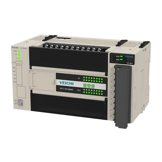
1.2 Outline
The outline of the VC1 series module is shown in the following figure by taking the example
of VC1-1614MAR.
P o w e r s u p p l y
R S - 4 8 5 I n t e r f a c e
S G 4 8 5 -
X 0
S / S
4 8 5 +
X 1
U S B I n t e r f a c e
L e f t e x t e n s i o n m o d u l e i n t e r f a c e
V E I C H I
B a t t e r y i n t e r f a c e
T e r m i n a l r e s i s t a n c e ( 1 2 0 Ω )
2 4 V
Y 0
Y 2
M o d e s e l e c t i o n s w i t c h
C O M
C O M 0
Y 1
Y 3 C O M 1 Y 5
S e r i a l p o r t ( R S - 2 3 2 )
PORT0 adopts the RS232, and the Mini DIN8 socket. 1 RS-485, USB interface is Type-C. The
right extension module interface is used for extension module connection, the left extension
module is used for communication module connection. RUN and STOP switched by MODE
selection. Two RS-485 terminal resistor, the resistance is 120Ω.
www.veichi.org
Tele
Zip code
Date of use
I n p u t s i g n a l t e r m i n a l
X 2
X 4
X 6
X 1 0 X 1 2 X 1 4
X 1 6
X 3
X 5
X 7
X 1 1 X 1 3 X 1 5
X 1 7
I n p u t s i g n a l s t a t u s i n d i c a t o r
R i g h t e x t e n s i o n m o d u l e i n t e r f a c e
P W R
R U N
E R R
S y s t e m w o r k i n g s t a t u s i n d i c a t o r
V C 1 - 1 6 1 4 M A R
O u t p u t s i g n a l s t a t u s i n d i c a t o r
Y 4
Y 6
Y 1 0 Y 1 2
Y 1 4
Y 7 C O M 2 Y 1 1 Y 1 3
Y 1 5
O u t p u t s i g n a l t e r m i n a l
1.3 Terminal Introduction
1.24 point module I/O points are shown below:
Input terminal:
Output terminal:
2.30 point module I/O points are shown below:
Input terminal:
Output terminal:
3. Power supply
The specification of PLC built-in power and power for extension modules is listed in the
following table.
Item
Unit
Min.
Power supply voltage
Vac
85
Input current
A
/
5V/GND
mA
/
Rated output
24V/GND
mA
/
current
24V/COM
mA
/
3 Digital input and output characteristics
3.1 Input Characteristic And Specification
The input characteristic and specs are shown as follows:
Item
High-speed input terminals X0~X7
Sigal input type
Source mode or sink mode, user set through "S/S" terminal
Input voltage 24Vdc
Electric
Input
3.3KΩ
impedance
paramet
ers
Input ON
External circuit resistance < 400Ω
Input OFF
External circuit resistance > 24KΩ
X0~X7 have digital filtering function. Filtering time: 0~60ms setting by user
Digital filter
programing.
Filtering
function
Hardware
Input terminals other than X0 ~ X7 are of hardware filtering. Filtering time: about
filter
10ms
X0~X7: high-speed counting, interrupt, and pulse catching
X0 and X1: up to 50kHz counting frequency
High speed function
X2~X5: up to 10kHz counting frequency
The sum of input frequency should be less than 60kHz
Common terminal
Only one common terminal: S/S
The counter input port has a corresponding maximum frequency limit.. Any frequency higher
than that may result in incorrect counting or abnormal system operation. Make sure that the
input terminal arrangement is reasonable and external sensors used are proper.
PLC provides a port "S/S" to select the input mode of the signal, which can be set to source
input mode or sink input mode. Connect "S/S" to "+24V", that is, set to sink input mode, and
NPN type sensor can be connected.
Input connection example
The following diagram shows an example of VC1-1614MAR in connection with an VC-
0808ENR, which realizes simple positioning control. The positioning signals from the PG are
input through high speed counting terminals X0 and X1, the limit switch signals that require
Rated
Max.
Note
220
264
Normal startup and operation
/
1.5
Input: 90Vac, 100% output
1500
/
The total power of outputs 5V/GND
/
and 24V/GND ≤ 30W.
1000
/
General input terminal
4.3kΩ
External circuit resistance < 400Ω
External circuit resistance > 24KΩ
1
Advertisement
Table of Contents

Subscribe to Our Youtube Channel
Related Manuals for Veichi VC1 Series

Summary of Contents for Veichi VC1 Series
- Page 1 Suggestion about improvement 1.2 Outline The outline of the VC1 series module is shown in the following figure by taking the example of VC1-1614MAR. P o w e r s u p p l y R S - 4 8 5 I n t e r f a c e...
- Page 2 + 2 4 V V E I C H I X 0 2 X 0 3 Other VC1 series PLC can be installed in DIN rail according to the above steps. X 0 5 X 0 4 + 5 V...
- Page 3 The recommended cable processing-method is shown in the following figure. 7. If you have any question, please contact the distributor or our company directly. ≤ 5.0 Veichi Electric Co., LTD. ≤ 5.0 Web: www.veichi.org Version: V1.0 Date : 2021-05-25...
Need help?
Do you have a question about the VC1 Series and is the answer not in the manual?
Questions and answers