
Related Manuals for South bend SB1118


Summary of Contents for South bend SB1118
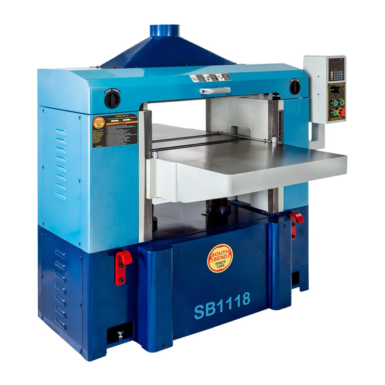
- Page 1 25" EXTREME-SERIES PLANER MODEL SB1118 ***Keep for Future Reference*** OWNER'S MANUAL South Bend Tools ® A Tradition of Excellence © December, 2021 by South Bend Tools For Machines Mfd. Since 10/21 (V1.12.21)
- Page 2 We highly value customer feedback on our manuals. If you have a moment, please share your experience using this manual. What did you like about it? Is there anything you would change to make it better? Did it meet your expectations for clarity, professionalism, and ease-of-use? South Bend Tools Technical Documentation Manager P.O. Box 2027 Bellingham, WA 98227 Email: manuals@southbendtools.com...
-
Page 3: Table Of Contents
Table of Contents INTRODUCTION ...............2 MAINTENANCE ............. 38 Identification ............2 Maintenance Schedule ........38 Description of Controls & Components ....3 Cleaning ............. 38 Internal Components ........... 5 Unpainted Cast Iron .......... 38 Product Specifications ........6 Lubrication ............39 Replacing Digital Readout Battery .... -
Page 4: Introduction
I N T R O D U C T I O N Model SB1118 For Machines Mfd. Since 10/21 INTRODUCTION Identification Headstock Headstock Cover Latches Cover Latches Dust Hood Dust Hood w/6" Port w/6" Port Digital Digital Readout Readout Control... -
Page 5: Description Of Controls & Components
I N T R O D U C T I O N For Machines Mfd. Since 10/21 Model SB1118 Description of Controls D. TABLE DOWN Button: Lowers table when pressed. When used in conjunction with digital readout, will lower table to a pre-set &... - Page 6 I N T R O D U C T I O N Model SB1118 For Machines Mfd. Since 10/21 Bed Roller Height Handle: Adjusts height of bed rollers from 0.002"–0.050". K. Table Height Scale: Shows elevation of table beneath cutterhead. The measurement...
-
Page 7: Internal Components
I N T R O D U C T I O N For Machines Mfd. Since 10/21 Model SB1118 Internal Components Figure Figure 4. Workpiece path and major planing components (side cutaway view). . Workpiece path and major planing components (side cutaway view). -
Page 8: Product Specifications
I N T R O D U C T I O N Model SB1118 For Machines Mfd. Since 10/21 Product Specifications Model SB1118 Model SB1118 Extreme-Series Planer 25" Planer with Helical Cutterhead Product Dimensions Weight................................1870 lbs. Width (side-to-side) x Depth (front-to-back) x Height............54-1/2 x 57 x 54-1/2 in. - Page 9 I N T R O D U C T I O N For Machines Mfd. Since 10/21 Model SB1118 Feed Horsepower............................3/4 HP Phase............................Single-Phase Amps................................8A Speed..............................2500 RPM Type..............................DC Motor Power Transfer ............................Belt Bearings....................Sealed & Permanently Lubricated...
-
Page 10: Safety
S A F E T Y Model SB1118 For Machines Mfd. Since 10/21 SAFETY Understanding Risks of Machinery Operating all machinery and machining equipment can be dangerous or relatively safe depending on how it is installed and maintained, and the operator's experience, common sense, risk awareness, working conditions, and use of personal protective equipment (safety glasses, respirators, etc.). - Page 11 S A F E T Y For Machines Mfd. Since 10/21 Model SB1118 Entanglement: Loose clothing, gloves, neckties, Chuck Keys or Adjusting Tools: Tools used to jewelry or long hair may get caught in adjust spindles, chucks, or any moving/...
-
Page 12: Additional Planer Safety
S A F E T Y Model SB1118 For Machines Mfd. Since 10/21 Additional Planer Safety Amputation, serious cuts, entanglement, or death can occur from contact with rotating cutterhead or other moving parts! Flying chips can cause eye injuries or blindness. Workpieces or knives thrown by cutterhead can strike nearby operator or bystanders with deadly force. -
Page 13: Preparation
P R E P A R A T I O N For Machines Mfd. Since 10/21 Model SB1118 PREPARATION Preparation Overview Required for Setup The purpose of the preparation section is to help The items listed below are required to you prepare your machine for operation. -
Page 14: Power Supply Requirements
P R E P A R A T I O N Model SB1118 For Machines Mfd. Since 10/21 Power supply requirements Power Supply Circuit Information A power supply circuit includes all electrical Requirements equipment between the main breaker box or fuse... - Page 15 P R E P A R A T I O N For Machines Mfd. Since 10/21 Model SB1118 Phase Converters Connection Type DO NOT use a static phase converter to create A permanently connected (hardwired) power 3-phase power—it can quickly decrease the life supply is typically installed with wires running of electrical components on this machine.
-
Page 16: Converting Voltage To 440V
For Machines Mfd. Since 10/21 Converting Voltage Loosen two wire nuts indicated in Figure 7. to 440V The Model SB1118 can be converted to 440V operation. This conversion consists of: 1) Disconnecting the planer from power, 2) rewiring 0 (Yellow) - Page 17 P R E P A R A T I O N For Machines Mfd. Since 10/21 Model SB1118 Open electrical box and locate transformer Remove cutterhead overload relay (see (see Figure 9). Figure 11) and replace with SDE RA-30 overload relay. Set amperage dial to 18.5A.
-
Page 18: Unpacking
P R E P A R A T I O N Model SB1118 For Machines Mfd. Since 10/21 Unpacking This item was carefully packaged to prevent damage during transport. If you discover any damage, please immediately call Customer Service at (360) 734-1540 for advice. You may... -
Page 19: Cleaning & Protecting
P R E P A R A T I O N For Machines Mfd. Since 10/21 Model SB1118 Cleaning & Protecting Avoid chlorine-based solvents, such as The unpainted surfaces are coated at the factory acetone or brake parts cleaner that may with a heavy-duty rust preventative that damage painted surfaces. -
Page 20: Location
P R E P A R A T I O N Model SB1118 For Machines Mfd. Since 10/21 Location Weight Load Refer to the Machine Specifications for the Physical Environment weight of your machine. Make sure that the surface upon which the machine is placed will... -
Page 21: Lifting & Moving
For Machines Mfd. Since 10/21 Model SB1118 Lifting & Moving Leveling The SB1118 comes with four cast-iron feet and four pre-installed hex bolts and hex nuts at each corner of the base for leveling the machine. This machine and its... -
Page 22: Anchoring To Floor
P R E P A R A T I O N Model SB1118 For Machines Mfd. Since 10/21 Anchoring to Floor Assembly Number of Mounting Holes ..........4 This machine must be fully assembled before it Size of Mounting Hardware ........ -
Page 23: Dust Collection
P R E P A R A T I O N For Machines Mfd. Since 10/21 Model SB1118 Dust Collection Using a straightedge as a guide (see Figure 19), rotate set screws installed in Step 2 until extension tables are level and flush with planer table. -
Page 24: Checking Gearbox Oil Levels
P R E P A R A T I O N Model SB1118 For Machines Mfd. Since 10/21 Checking Gearbox Oil Table Gearbox Remove lower access panel on right-hand Levels side of machine. Before starting the machine for the first time, Remove gearbox oil fill plug (see Figure 23). -
Page 25: Power Connection
P R E P A R A T I O N For Machines Mfd. Since 10/21 Model SB1118 Power Connection Connecting power supply wires to machine without first disconnecting power supply may result in serious injury or death. Electrocution or fire... -
Page 26: Test Run
P R E P A R A T I O N Model SB1118 For Machines Mfd. Since 10/21 Test Run Twist EMERGENCY STOP button clockwise until it pops out (see Figure 26). This resets switch so machine can start. After all preparation steps have been completed, the machine and its safety features must be tested to ensure correct operation. - Page 27 P R E P A R A T I O N For Machines Mfd. Since 10/21 Model SB1118 — If machine does not start, the EMERGENCY STOP button safety feature is working correctly. — If machine does start (with EMERGENCY STOP button pushed in), immediately disconnect power to machine.
-
Page 28: Inspections & Adjustments
P R E P A R A T I O N Model SB1118 For Machines Mfd. Since 10/21 Inspections & Adjustments After approximately 16 hours of operation, V-belts will stretch and seat into pulley grooves and need to be properly tensioned to... -
Page 29: Operation
Regardless of the content in this section, workpiece into front of planer again. South Bend Tools will not be held liable for accidents caused by lack of training. Operator continues process until desired workpiece thickness is achieved, then turns planer OFF. -
Page 30: Stock Inspection & Requirements
O P E R A T I O N Model SB1118 For Machines Mfd. Since 10/21 Stock Inspection & Wood Types Requirements The species of wood, as well as its condition, greatly affects the depth of cut the planer can effectively take with each pass. -
Page 31: Planing Tips
O P E R A T I O N For Machines Mfd. Since 10/21 Model SB1118 Planing Tips Common Cutting Problems • Inspect your lumber for twisting or cupping, and surface cupped side on a jointer if necessary before planing workpiece. - Page 32 O P E R A T I O N Model SB1118 For Machines Mfd. Since 10/21 Pitch & Glue Build-up Snipe Problem: Occurs when board ends have more Problem: Glue and resin buildup on the rollers material removed than the rest of the board.
-
Page 33: Depth Of Cut
O P E R A T I O N For Machines Mfd. Since 10/21 Model SB1118 Depth of Cut Using Table Height Handwheel Material Thickness Range Minimum – Maximum Stock Thickness ..⁄ "– 9" The table height handwheel is located on the... -
Page 34: Using Table Up/Down Buttons
O P E R A T I O N Model SB1118 For Machines Mfd. Since 10/21 Using TABLE UP/ Using Digital Readout DOWN Buttons The digital readout can be used to store up to ten preset table positions, move the table to a preset... - Page 35 O P E R A T I O N For Machines Mfd. Since 10/21 Model SB1118 Digital Readout Buttons Changing Digital Readout Values Adding/Subtracting Distances The digital readout values can be expressed In SINGLE mode, distances can be added to or either in millimeters or inches with the MM/ subtracted from the current position of the table.
-
Page 36: Setting Feed Rate
O P E R A T I O N Model SB1118 For Machines Mfd. Since 10/21 Feed Rate Setting Feed Rate Press any key from "0" to "9" to store target value. The number of key pressed will INCH appear to right of "ProG" in target window. -
Page 37: Bed Roller Height
O P E R A T I O N For Machines Mfd. Since 10/21 Model SB1118 Bed Roller Height Bed Roller Height To adjust bed roller height: DISCONNECT MACHINE FROM POWER! The correct height of the bed rollers will vary,... -
Page 38: Rotating/Replacing Cutterhead Inserts
O P E R A T I O N Model SB1118 For Machines Mfd. Since 10/21 Cutterhead Inserts Rotating/Replacing Remove any sawdust or debris from head of insert, Torx screw, and surrounding area (see Figure 36). Cutterhead Inserts The spiral cutterhead is equipped with 4-sided indexable carbide inserts. -
Page 39: Accessories
To reduce this risk, only install accessories recommended by South Bend or Grizzly. Refer to Grizzly’s website or latest catalog for additional recommended accessories. W1218A—Rotacator Precision Planer Tool... -
Page 40: Maintenance
For Machines Mfd. Since 10/21 MAINTENANCE Maintenance Schedule Cleaning Cleaning the Model SB1118 is relatively easy. Vacuum excess wood chips and sawdust, and wipe off the remaining dust with a dry cloth. If Always disconnect any resin has built up, use a resin dissolving machine from power before cleaner to remove it. -
Page 41: Lubrication
Open-End Wrench 19mm ........1 The table rides on two leadscrews that are Since all bearings on the Model SB1118 are protected by dust boots. Raise the table all the sealed and permanently lubricated, simply leave way up, and loosen the dust boots to access the them alone until they need to be replaced. - Page 42 M A I N T E N A N C E Model SB1118 For Machines Mfd. Since 10/21 Drive chain and sprockets Drive Chains & Sprockets Table Height Chains & Sprockets Grease Type ..T26419 or NLGI#2 Equivalent Grease Type ..T26419 or NLGI#2 Equivalent Amount ...........
- Page 43 M A I N T E N A N C E For Machines Mfd. Since 10/21 Model SB1118 Gearbox Oil Table Gearbox Remove the upper access panel on the right-hand Oil Type ....T28088 or ISO 150 Equivalent side of the machine. Remove the oil fill plug (see Oil Amount (Cutterhead/Feed Gearbox) ..
-
Page 44: Replacing Digital Readout Battery
M A I N T E N A N C E Model SB1118 For Machines Mfd. Since 10/21 Replacing Digital Table Ways Oil Type ....SB1365 or ISO 68 Equivalent Readout Battery Oil Amount ..........Thin Coat Frequency ....Every 40 Hours of Operation If the digital readout stops operating correctly, the D battery must be replaced. -
Page 45: Anti-Kickback Fingers
M A I N T E N A N C E For Machines Mfd. Since 10/21 Model SB1118 Anti-Kickback Fingers Check the anti-kickback fi ngers regularly to ensure they swing freely and easily. If the fi ngers do not swing freely and easily, fi rst clean them... -
Page 46: Tensioning/Replacing Belts
S E R V I C E Model SB1118 For Machines Mfd. Since 10/21 Tensioning/Replacing Remove lower rear panel to access motor mount hex nuts (see Figure 53). Belts Motor Mount Motor Mount Three V-belts transfer power from the motor... - Page 47 S E R V I C E For Machines Mfd. Since 10/21 Model SB1118 Tensioning/Replacing Timing Belt To adjust timing belt tension, gently press on feed motor output shaft (see Figure 55), and Items Needed tighten cap screws when tension is correct.
-
Page 48: Setting Feed Rollers, Chip Breaker & Pressure Bar Heights
S E R V I C E Model SB1118 For Machines Mfd. Since 10/21 Setting Feed Rollers, Using a Rotacator Items Needed Chip Breaker & Hex Wrench 3mm ..........1 Open-End Wrench 10mm ........1 Pressure Bar Heights Metal Shims .......... As Needed Rotacator (see Page 37) ........ - Page 49 S E R V I C E For Machines Mfd. Since 10/21 Model SB1118 Loosen jam nuts and use set screws (see 10. Using same "0" reference on Rotacator Figure 59) on each side of infeed roller to dial from Step 5, perform similar steps...
- Page 50 S E R V I C E Model SB1118 For Machines Mfd. Since 10/21 Using Wood Blocks Raise the headstock cover. Items Needed Use handwheel to adjust table height until Hex Wrench 3mm ..........1 there is a 0.020" gap between edge of a Open-End Wrench 10mm ........
-
Page 51: Adjusting Feed Roller Spring Tension
S E R V I C E For Machines Mfd. Since 10/21 Model SB1118 Adjusting Feed Roller Tools Needed Hex Wrench 4mm ..........1 Open-End Wrench 14mm ........1 Spring Tension To adjust feed roller spring tension: The infeed and outfeed rollers keep the DISCONNECT MACHINE FROM POWER! workpiece moving through the planer. -
Page 52: Calibrating Table Height Indicator
S E R V I C E Model SB1118 For Machines Mfd. Since 10/21 Calibrating Table Replacing Feed Motor Height Indicator Brushes The indicator on the depth scale should match This planer is equipped with a universal motor the value shown in the bottom window of the that uses two carbon brushes to transmit digital readout. -
Page 53: Checking Pulley Alignment
S E R V I C E For Machines Mfd. Since 10/21 Model SB1118 pulley alignment Checking Pulley Loosen (4) hex nuts that secure motor to mounting plate (see Figure 68), shift motor until pulleys are aligned, then tighten hex Alignment nuts. -
Page 54: Adjusting Table Parallelism
S E R V I C E Model SB1118 For Machines Mfd. Since 10/21 Adjusting Table Table Parallelism Adjustments The table is adjusted by turning the elevation Parallelism leadscrew housing brackets underneath the table. Maximum Allowable Tolerances Cutterhead/Table Side-to-Side .....0.003"... -
Page 55: Tensioning Table Height Chain
S E R V I C E For Machines Mfd. Since 10/21 Model SB1118 Tensioning Table Keeping Rotacator dial at "0", position it under right-hand edge of cutterhead and find bottom dead center (BDC). Height Chain — If value of measurement on right-hand The table height chain is located beneath the side of table differs less than 0.003"... -
Page 56: Adjusting Table Gibs
S E R V I C E Model SB1118 For Machines Mfd. Since 10/21 Adjusting Table Gibs Calibrating Bed Rollers The function of the table gibs is to eliminate The bed rollers provide even planing pressure excessive play in the table movement. Tight gibs from side to side and front to back by pushing the make table movement more accurate but stiff. -
Page 57: Calibrating Digital Readout
PROG INCH S E R V I C E For Machines Mfd. Since 10/21 Model SB1118 START MANUAL Calibrating digital readout SINGLE Calibrating Digital Press ENTER key . A light in (top) STOP PROG target window will blink, and "OriGin" will... -
Page 58: Troubleshooting
TROU B LESHOOTI NG Model SB1118 For Machines Mfd. Since 10/21 TROUBLESHOOTING If you need replacement parts, or if you are unsure how to do any of the solutions given here, feel free to call us at (360) 734-1540. Symptom... - Page 59 TROU B LESHOOTI NG For Machines Mfd. Since 10/21 Model SB1118 Symptom Possible Cause Possible Solution 1. Correct phase polarity (Page 24). Table moves up 1. Power connections wired out of when it should phase. move down. Table will not 1.
- Page 60 TROU B LESHOOTI NG Model SB1118 For Machines Mfd. Since 10/21 Symptom Possible Cause Possible Solution Consistent 1. Knots or conflicting grain direction 1. Inspect workpiece for knots and grain direction; use only clean stock (Page 28). chipping pattern. in workpiece.
-
Page 61: Electrical
E L E C T R I C A L For Machines Mfd. Since 10/21 Model SB1118 ELECTRICAL Electrical Safety Instructions These pages are accurate at the time of printing. In the constant effort to improve, however, we may make changes to the electrical systems of future machines. Study this section carefully. If you see differences between your machine and what is shown in this section, call Technical Support at (360) 734-1540 for assistance BEFORE making any changes to the wiring on your machine. -
Page 62: Electrical Overview
E L E C T R I C A L Model SB1118 For Machines Mfd. Since 10/21 Electrical Overview Electrical Overview Headstock Cover Safety Switch (Page 66) Table Lower Limit Switch (Page 66) Control Panel Box (Page 64) Power Supply Junction Box (Page 67) -
Page 63: Electrical Box
E L E C T R I C A L For Machines Mfd. Since 10/21 Model SB1118 Electrical Box Figure Figure 76. Electrical box components. . Electrical box components. Power supply wiring DISCONNECT SWITCH (as recommended ) Ground Electrical Box... -
Page 64: Electrical Box Wiring Diagram
E L E C T R I C A L Model SB1118 For Machines Mfd. Since 10/21 Electrical Box Wiring Electrical Box Wiring Diagram Electrical Box Transformer GDM 40VA 220V 440V 24V 220V 1/L1 3/L2 5/L3 Contactor MA-55 2/T1 4/T2... -
Page 65: Control Box
E L E C T R I C A L For Machines Mfd. Since 10/21 Model SB1118 Control Box Figure Figure 77. Control box wiring. . Control box wiring. South Bend Tools -63-... -
Page 66: Control Box Wiring Diagram
E L E C T R I C A L Model SB1118 For Machines Mfd. Since 10/21 Control Box Wiring Control Box Wiring Diagram Control Panel Digital Readout M15S-DC24V WARNING! 0V 1 2 3 4 SHOCK HAZARD! Disconnect power before working on D Battery wiring. -
Page 67: Main Motor Wiring Diagrams
E L E C T R I C A L For Machines Mfd. Since 10/21 Model SB1118 Motor Wiring Main Motor Wiring Diagrams 220V 440V U5 U1 V5 V1 W1 W5 Rewired for 440V Operation To Electrical Box (Pg. 62) -
Page 68: Electrical Component Wiring Diagrams
E L E C T R I C A L Model SB1118 For Machines Mfd. Since 10/21 Electrical Components Electrical Component Wiring Diagrams Safety Switch Pg. 62 (To Electrical Box) Figure Figure 78. Headstock cover safety switch. . Headstock cover safety switch. -
Page 69: Electrical Component Photos
E L E C T R I C A L For Machines Mfd. Since 10/21 Model SB1118 Electrical Component Photos Electrical Component Photos Upper Limit Switch Upper Limit Switch Figure Figure 81. Power supply junction box (220V). . Power supply junction box (220V). -
Page 70: Parts
P A R T S Model SB1118 For Machines Mfd. Since 10/21 PARTS Base & Motors 143-1 143-2 143-3 143-5 143-4 192-8 192-10 192-11 180-1 192-12 180-2 192-9 180-3 192-7 192-3 180-4 180-5 192-5 192-4 192-6 380-2 380-3 380-4 South Bend Tools... - Page 71 P A R T S For Machines Mfd. Since 10/21 Model SB1118 Base & Motors Parts List PART # DESCRIPTION PART # DESCRIPTION PSB1118001 WORM GEARBOX ASSEMBLY PSB1118170 ROLL PIN 6 X 25 PSB1118002 BUTTON HD CAP SCR M6-1 X 10...
- Page 72 P A R T S Model SB1118 For Machines Mfd. Since 10/21 Base & Motors Parts List (Cont.) PART # DESCRIPTION PART # DESCRIPTION PSB1118209 INT RETAINING RING 68MM PSB1118251 POWER SUPPLY JUNCTION BOX PSB1118210 BALL BEARING 6008-2NSE PSB1118252 TERMINAL BLOCK...
-
Page 73: Column
P A R T S For Machines Mfd. Since 10/21 Model SB1118 Column 242 234 South Bend Tools -71-... - Page 74 P A R T S Model SB1118 For Machines Mfd. Since 10/21 Column Parts List PART # DESCRIPTION PART # DESCRIPTION PSB1118002 BUTTON HD CAP SCR M6-1 X 10 PSB1118110 CAP SCREW M8-1.25 X 25 PSB1118005 LOCK WASHER 8MM PSB1118142 CAP SCREW M8-1.25 X 40...
-
Page 75: Headstock
P A R T S For Machines Mfd. Since 10/21 Model SB1118 Headstock 159-6 159-5 159-4 159-3 159-2 159-1 43 130 43 94 58-3 58-2 47 22 58-1 South Bend Tools -73-... - Page 76 P A R T S Model SB1118 For Machines Mfd. Since 10/21 Headstock Parts List PART # DESCRIPTION PART # DESCRIPTION PSB1118003 DEFLECTION PLATE PSB1118083 SHAFT PSB1118004 CAP SCREW M8-1.25 X 30 PSB1118084 COMPRESSION SPRING 5 X 29 X 90...
-
Page 77: Table
P A R T S For Machines Mfd. Since 10/21 Model SB1118 Table 125 126 138 139 South Bend Tools -75-... - Page 78 P A R T S Model SB1118 For Machines Mfd. Since 10/21 Table Parts List REF PART # DESCRIPTION PART # DESCRIPTION PSB1118005 LOCK WASHER 8MM PSB1118122 PSB1118007 HEX NUT M8-1.25 PSB1118124 ROLLER PSB1118014 LOCK WASHER 5MM PSB1118125 SET SCREW M5-.8 X 8...
-
Page 79: Gearbox
P A R T S For Machines Mfd. Since 10/21 Model SB1118 Gearbox 107-2 107-3 107-1 107-1 107-4 107-31 107-7 107-5 107-10 107-1 107-9 107-6 107-11 107-7 107-22 107-1 107-12 107-13 107-26 107-17 107-14 107-13 107-31 107-15 107-1 107-18 107-8... -
Page 80: Electrical Components
P A R T S Model SB1118 For Machines Mfd. Since 10/21 Electrical Components 337-2 337-1 381-1 381-2 South Bend Tools -78-... - Page 81 P A R T S For Machines Mfd. Since 10/21 Model SB1118 Electrical Components Parts List REF PART # DESCRIPTION PART # DESCRIPTION PSB1118002 BUTTON HD CAP SCR M6-1 X 10 PSB1118353 LIMIT SWITCH MJ2-1307 15A 125V PSB1118097 PHLP HD SCR M4-.7 X 30...
-
Page 82: Machine Labels
The owner of this machine MUST maintain the original location and readability of these safety labels. If any label is removed or becomes unreadable, REPLACE that label before using the machine again. Contact South Bend Tools at (360) 734-1540 or www.southbendtools.com to order new labels. -
Page 83: Warranty
WARRANTY Warranty This quality product is warranted by South Bend Tools to the original buyer for 2 years from the date of purchase. This warranty does not apply to consumable parts, or defects due to any kind of misuse, abuse, negligence, accidents, repairs, alterations or lack of maintenance. We do not reimburse for third party repairs. - Page 84 southbendtools.com Printed In Taiwan #MN22172...
Need help?
Do you have a question about the SB1118 and is the answer not in the manual?
Questions and answers