Table of Contents
Advertisement
Quick Links
Advertisement
Table of Contents

Related Manuals for Magneti Marelli MM-WB1024

Summary of Contents for Magneti Marelli MM-WB1024
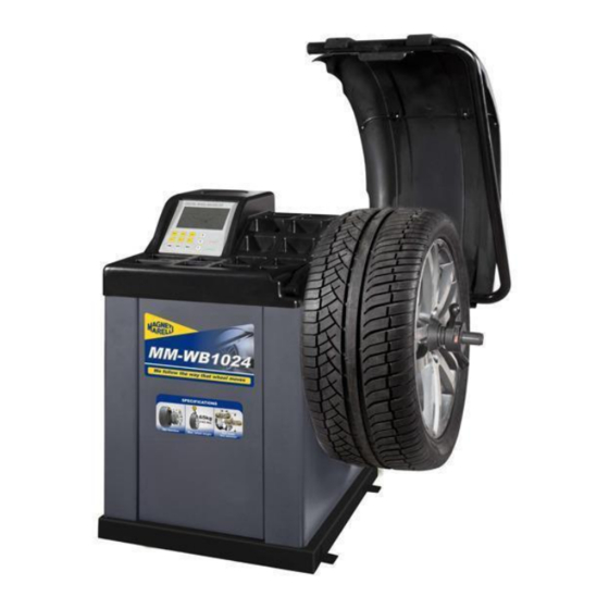
- Page 1 Wheel balancer MM-WB1024 User’s manual 007935017275 007935017280 Magneti Marelli Aftermarket Spółka z.o.o. Plac Pod Lipami 5, 40-476 Katowice Tel.: + 48 (032) 6036107, Faks: + 48 (032) 603-61-08 e-mail: checkstar@magnetimarelli.com www.magnetimarelli-checkstar.pl...
-
Page 2: Specification And Features
1. Introduction An imbalanced wheel will make the wheel jump and steering wheel wobble while driving. It can baffle the driver to drive, aggrandize the cleft of combine area of steering system, damage the vibration damper and steering parts, and increase the probability of the traffic accidents. A balanced wheel will avoid all these problems. - Page 3 Dimensions: 960mm×760mm×1160mm 2.2 Features LCD screen display, intuitive and flexible user interface. Various balancing modes can carry out counterweights to stick, clamp, or hidden stick etc. Input data of rim automatically by measure scale. Intelligent self-calibrating and measure scale self-labeling function. Self fault diagnosis and protection function.
- Page 4 The microcomputer system is made up of the LSI such as new high speed MCU CPU system and keyboard. Automatic measure scale. Testing speed and positioning system consists of gear and opto-electronic coupler. Two-phase asynchronous motor supplies and control circuit. Horizontal and vertical pressure sensor.
- Page 5 Locking nut Adapter (cone) Counterweight (100g) Protection hood (optional) 1 4.2 Installing machine 4.2.1 The balancer must be installed on the solid cement or similar ground, unsolidified ground can bring measuring errors. 4.2.2 There should be 50cm around the balancer in order to operate conveniently. 4.2.3 Nail anchor bolts on the base’s mounting hole of balancer to fix the balancer.
- Page 6 5 LCD control panel and function keys Figure 5-1 Push buttons, manual DISTANCE (a) setting Push buttons, manual WIDTH (b) setting Push buttons, manual DIAMETER (d) setting Push button , selection of “ALU” mode of correction Push buttons for recalculation and self-calibration Selection, “STATIC”...
- Page 7 Push button, imbalance display pitch and threshold 11- Push button, optimization of imbalance and split imbalance 12-Counter weights installation posotion diagram. 13-Inside balance weight position light 14-Outside balance weight position light 15-Display the tire medial imbalance values or distance values 16-Display static imbalance value or width value 17-Display the tire lateral imbalance value or diameter values N.B.
- Page 8 Figure 6-1 Figure 6-2 6.2.3 Install wheel and cone on main shaft. Ensure the cone can clamp the wheel before screwing handle. Wheel can rotate after screwing down. 6.3 Demounting the Wheel 6.3.1 Demount the handle and cone. 6.3.2 Put the wheel up, and then take it down from main shaft. Note: do not slip wheel on main shaft to prevent main shaft from scuffing while installation and demounting the Wheel 7 The input methods of date of rim...
- Page 9 Figure 7-1 7.2 Date input method for normally dynamic balance mode 7.2.1 After the power-on of the machine, it enter the normal balance mode 7.2.2 Input date of rim: Figure 7-2 Rotate the measure scale, pull the scale head to inside concave on the edge of the rim, etc figure 7-2, first LED all off, then display ect figure 7-3,waiting put back scale.
- Page 10 7.2.3 When measure values with fact value of rim differ, you need selfcalibration of scales then measure again or manual input date of rim. 7.2.4 Input date of rim width 7.2.4.1 Put width scale head on rim outside edge, ect figure 7-4. First LED all off, then display ect figure 7-5, waiting put back scale.
- Page 11 Figure7-6 Move the calliper, against the calliper head to the middle of rim. As the figure 7-7. Now the display screens whole closed. When finish measure, the machine makes a warning voice as “Bi” and show the figure 7-3. Figure7-7 Put the calliper back.
-
Page 12: Calibration Of Measure Scale
Figure7-9 7.5.2 Date input method for ALU-S2 balance mode As the figure 7-10,move the calliper to the inside of rim (FI),measure the inside range (aI) and diameter (dI). When the machine displays figure 7-3,go on move calliper to outside of rim(FE) to measure the outside ranger of rim (aE) and diameter (dE). After that the machine displays Fig.7-11 enters into ALU-S2 mode. - Page 13 8.1 Calibration of rim distance scale 8.1.1 Press and hold STOP key and press FINE key, ect figure 8-1(press STOP key or C key to exit). Figure 8-1 8.1.2 Move scale to 0(zero) position, press ALU key, ect figure 8-2(press STOP key or C key to exit).
- Page 14 Figure 8-4 8.2.2 Press d+ or d- adjust value to current rim diameter value, press ALU key, ect figure 8- Figure 8-5 8.2.3 Move scale, put scale head on the inside edge of rim ect figure 7-2, press ALU key, ect figure 8-3,self-calibration end, put back scale. 8.3 Calibration of width scale 8.3.1 Press and hold STOP key and press b+ or b-, ect figure 8-6, (press STOP key to exit);...
- Page 15 9 The Self-calibrating of Balancer The self-calibrating of balancer was finished before ex-factory, but the system parameter may vary because of long-distance transportation or long-term use, which may cause error. Therefore, users can make self-calibrating after a period of time. 9.1 After the power-on of the machine, the initialization is finished ect figure 7-1,install a can clip counterweight and comparatively balance middle size tyre, follow step 7 input date of rim;...
- Page 16 Figure 9-2 9.4 After axis stop, ect figure 9-3, calibration end. Demount tyre, now balancer ready to work. Figure 9-3 NB:when you doing self-calibration, input date of rim must be correct,100 gram counterweight must be correct, otherwise self-calibration result will be wrong, wrong self- calibration will be make balancer measure precision decline.
- Page 17 Figure 10-1 Figure 10-2 10.1.2 ALU balance mode switch key (ALU key), switch CPU system between ALU-1~ALU-5 mode. ALU-1mode:stick counter weight on the inside rim at the shoulder location and the inside of spoke figure10-3。 ALU-2 mode:stick counter weights on the inside of rim and inside of spoke as figure 10-4.
- Page 18 Figure 10-5 Figure 10-6 ALU-5mode: stick counter weights on the insider of rim at shoulder location and clamp counter weights at the outside edge of rim as figure 10-7. Figure 10-7 10.1.3 Counterweight split and Hidden-Stick Mode: ALU-S mode, if the outside (inside of spoke) counterweight position between of two spokes, ALU-S mode can split the counterweight for two.
- Page 19 10.2.3 Slowly spin wheel, when inside counterweight position indicator light(figure 5-1(13)) all on, clip correspond counterweight on 12 o’clock position on inside of rim, ect figure10-9; 10.2.4 Slowly spin wheel, when outside counterweight position indicator light(figure 5- 1(14)) all on, clip correspond counterweight on 12 o’clock position on outside of rim, ect figure10-10;...
- Page 20 10.4.3 Lay down protect hood and press START key, wheel spinning, after stop middle LED display wheel static imbalance weight, when middle LED display OPT, can choice imbalance optimize; 10.4.4 Slowly spin wheel, when both side counterweight position indicator light (figure 5- 1(8), (9)) all on, stick counterweight on 12 o’clock position middle of rim.
- Page 21 Figure10-12 ★ALU-S1 process of automatic stickup partition Counter weight 10.5.5 Follow figure 7.5.1 input date of rim; 10.5.6 Lay down protect hood and press START key, wheel spin, after stop two side display wheel both side imbalance weight, when middle display OPT, can choice imbalance optimize;...
- Page 22 Figure10 - 14 Figure10 - 15 10.6 ALU-S2 balance mode operation process ★ALU-S2 Process of manual stickup counterweight 10.6.1 Follow figure 7.5.2 input date of rim; 10.6.2 Lay down protect hood and press START key, wheel spin, after stop two side display wheel both side imbalance weight, when middle display OPT, can choice imbalance optimize;...
- Page 23 10.6.6 Lay down protect hood and press START key, wheel spin, after stop two side display wheel both side imbalance weight, when middle display OPT, can choice imbalance optimize; 10.6.7 Slowly spin wheel, when inside counterweight position indicator light(figure 5-1(13)) all on, stick counterweight on 12 o’clock position on inside of rim.
- Page 24 10.7.2 Stick inside operation same 10.5.3(ALU-S1)or10.6.3(ALU-S2); 10.7.3 Slowly spin wheel, when outside counterweight position indicator light(figure 5-1(14)) all on, stick counterweight on 12 o’clock position outside of rim, ect figure 10-12 right side; 10.7.4 Slowly spin wheel again, when outside counterweight position indicator light(figure 5-1(14)) all on, find second position, stick counterweight on 12 o’clock position outside of rim, ect figure 10-12 right side;...
- Page 25 Figure10-17 8.1Accord 7.2input tyre data; 10.8.2 Press D key and ALU key,go to ALU_X mode,as figure 10-17; 10.8.3 Put down shelter press START key,the tyre spin tyre. After tyre stop rotating, two sides digital tube show the unbalance data of two sides tyre. 10.8.4 Slowly spin wheel, when inside counterweight position indicator light(figure 5-1(13)) all on, stick counter weight on the inside of rim at 12 o’clock location.
- Page 26 Figure 11-1 Use chalk mark a reference point on the flange plane and rim and tyre, use tyre changer exchange rim and tyre 180°;Reinstall wheel on the balancer and make sure mark of reference point between the flange plane and rim must be on the same potion. press START key, display ect figure 11-2;...
- Page 27 11.2 Before testing of process imbalance optimize directly Turn on the power, installation wheel, press OPT key, left side display OPT, press START key, display ect figure 11-1,then follow 11.1 step to operation. Press STOP key to stop operation. 12 Gram and Oz conversion operation This operation for counterweight maund conversion (gram-Oz).
-
Page 28: Other Function Settings
Boot interface (figure7-1), Press STOP key and d+ key or d-, long measure (figure 5-1(16)) display value B and (figure 5-1(17)) display value D can be change between INCH/MM. If in the LED display window right underside have a radix point mean currently long measure is INCH, if not, long measure is MM. -
Page 29: Machine Self Test Function
Figure 15-1 15.2 Key-tone clue on function settings This function can turn on or turn off key-tone, even turn on this function, every time press key, system will be emit a “dI” of tone, even turn off this function, press key not tone. From 15.1 press a+ enter settings, ect figure 15-2,right side display ON denotation function on, display OFF denotation function off. - Page 30 This function will be check all kinds input signal whether right working and provide gist for trouble analyses. 16.1 LED check Press D key, stroke on the LCD will all lit up. This function can check whether the LCD damaged, press C key to exit, after about 5 seconds display ect figure 16-1,enter position sensor check.
- Page 31 Figure 16-2 16.4 Diameter sensor signal check This function can be check diameter sensor and main board signal circuit whether damage. From 16.3 press ALU key enter, ect figure 16-3, turn measure scale, value will be change, anticlockwise turn, value increase, clockwise press turn, value minish. Press ALU key, enter press sensor signal check.
- Page 32 From 16.5 press ALU key enter, ect figure 16-5, gently press principal axis, right and left LED display value will be change, press ALU key to enter press sensor signal check. Press C key exit. Figure 16-5 17 Safety Protection and Trouble Shooting 17.1 Safety protection 17.1.1 Under the circumstance of operation, if the machine does not operate normally,...
-
Page 33: Maintenance
Figure 17-1 17.2.5 Automatic measure rim, advert display date whether difference with trim size of rim, if difference, need measure scale self-calibration; 17.2.6 If turn on the power have not display, check power switch indicator light whether working, if not, check power supply first, then check power supply board and computer board and cable connections;... - Page 34 18.1.1.2 Unlash the screw of the motor, move the motor till the belt’s tension is proper, and emphatically press the belt downwards about 4mm. 18.1.1.3 Tighten the screw of the motor and cover the hood. 18.1.2 Check whether the wire of electricity part connects reliably. 18.1.3 Check whether the pressed screw of the main axis is loose.
- Page 35 Figure 18-1 19 Trouble-error code list When balancer display hint of error, can follow consult below list to remove the trouble: meanings cause remedy principal axis 1.motor fault 1.change motor rr 1 not spin or have not 2.change position 2.position sensor fault spin signal 3.power supply board sensor...
- Page 36 The rotation is 1. change position sensor position sensor fault lower than rr 2 2.repeat impacting wheel wheel not impacting 60r/min or weight too light 3. change motor motor fault 4.adjust driving belt driving belt too elasticity loose or too tighten 5.
-
Page 37: Power Supply Layout Diagram
20 Power supply layout diagram 20.1 220 V Connection 20.2 380 V Connection... -
Page 38: Exploded Drawings
21 Exploded drawings... -
Page 43: Spare Parts List
22 Spare parts list Code Description Code Description B-014100251-0 B-007060081-0 Screw Screw B-040103030-1 B-014100451-0 Washer Screw PX-800020000- B-001100001-0 Base PX-800010000- PX-100200200- Body -101 Shaft P-000009002-0 ABS Washer P-000009000-0 P-120210000-0 Tools hang -214 Spring S-060000210-0 P-120250000-0 Bobbin winder Power switch -212 pulley S-025000135-0 S-132000010-0... - Page 44 B-024050251-0 B-040103030-1 Screw Washer D-010100300- B-014100251-0 Resistor Screw P-100120100-0 B-050100000-0 Washer P-800190000-0 Head with tools- B-040102020-1 tray Washer S-140007280-0 PZ-000040100- Position Pick-up Computer board -306 Board 82330 S-140007280-0 display B-024030061-0 board Screw 82331 PX-823100000-0 support 800 - board Thread 82332 S-115008230-0 800 - P-100420000-0...
- Page 45 Code Description Code Description P-870011800-0 Magnet 040040000-1 Flat washer 112082901-0 Complete ruler head 050040000-0 Spring washer P-870011001-0 board Installation 870010900-0 assembly spring B-007060081-0 Revolve shaft 870010100-0 Screw assembly B-019420161-0 Screw -213 132000010-0 Gauge sensor B-007040061-0 Screw 024350281-0 Screw B-024030081-0 017030251-0 Screw Screw B-050030000-0...
-
Page 46: Accessories List
Descriptio n Descriptio n Code Code Rubber B-010060301-0 C-221-640000-A cover Screw B-040061412-1 B-001-060001-0 Washer B-004060001-1 B-040-061412-1 Washer PX-100020200- Brake lever B-014-100251-0 Screw PX-800-020300- B-001120001-0 Foot lever P-000002001-1 Brake pads C-200-380000-0 Spring PX-100-020400- Connectin g B-004060001-1 Accessories list Specification options 1: 36 2: 40... - Page 47 CODE ITEM PHOTO 1:φ 36 1:S-100-036000-1 1# CONE 2:φ 2:S-100-040000-1 1:φ 1:S-100-036000-2 2# CONE 2:S-100-040000-2 φ40 1:φ 1:S-100-036000-3 3# CONE 2:φ 2:S-100-040000-3 1:φ 1:S-100-036000-4 4# CONE 2:φ 2:S-100-040000-4 1:P-005-100000-0 φ36 COMPLETE QUICK RELEASE NUT 2:φ 2:P-005-100040-0 1:Tr 1:P-100-400000-0 THREADED SHAFT 2:Tr 2:P-828-400000-0 Y-032-020823-0...
- Page 48 S-108-000010-0 PLIER P-100-490000-0 PLASTIC LID P-000-001002-0 RUBBER BUFFER For one item with two codes, please select as per Specification Options, or select by measuring real object.
-
Page 49: System Circuit Diagram
Attach figure 1 System circuit diagram Magneti Marelli Aftermarket Spółka z.o.o. Plac Pod Lipami 5, 40-476 Katowice Tel.: + 48 (032) 6036107, Faks: + 48 (032) 603-61-08 e-mail: checkstar@magnetimarelli.com www.magnetimarelli-checkstar.pl...
Need help?
Do you have a question about the MM-WB1024 and is the answer not in the manual?
Questions and answers