Table of Contents
Advertisement
Quick Links
Advertisement
Table of Contents

Subscribe to Our Youtube Channel
Summary of Contents for Walther-Werke basicEVO
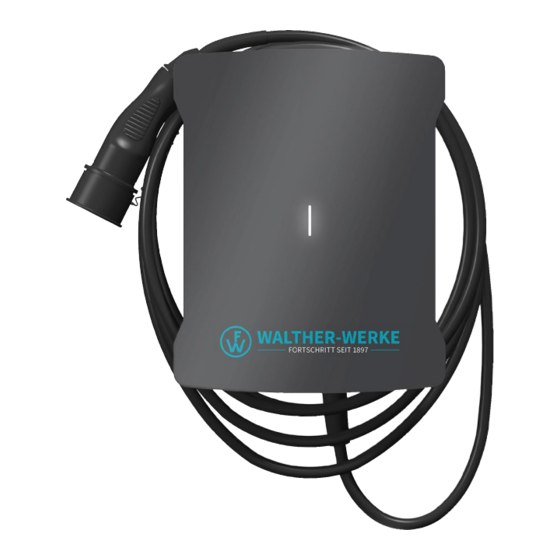
- Page 1 WALLBOX basicEVO | basicEVO PRO INSTRUCTION MANUAL walther-werke.de/service...
- Page 2 English...
- Page 3 PRO 1 x Wallbox-Cover 1 x Wallbox 4 x M4x10 T20 2 x EADR25 basicEVO PRO 2 x ESKV25 1x MFD 25/03/073 Chapter 1...
- Page 4 6A/0A 0A/6A...
- Page 5 CAT6a max. 500m 15mm 60mm 70mm...
- Page 6 VIII...
- Page 7 e.g. HEMS...
- Page 9 XIII e.g. HEMS...
-
Page 11: Table Of Contents
2.3 Bus system with central wiring in distributor Local and external load management Prerequisites 3.2 Bus topology 3.3 Check-list for local load management 3.4 Check-list for external load management Configuration of the Wallboxes 4.1 Configuration of maximum (switch S1) and minimum (switch S3) charging current (per Wallbox) 4.2 Switch S2 4.3 Switch S4 4.4 Switch S5 4.5 Switch S6 Bus protocol (external load management) 5.1 Modbus connection 5.2 Functions supported by the Modbus protocol Checking load management Table Modbus Register – Wallbox basicEVO PRO 17... -
Page 12: Introduction
English Introduction load management system to the next Wallbox. Please note: The Wallbox basicEVO PRO is used to charge plug-in • Two conductors per bus line are used. hybrid or electric vehicles. Several basicEVO PRO • Connect the bus using two separate bus lines each Wallbox units can be operated in an integrated between the Wallboxes (Line in and Line out). network. This enables the power distribution to be monitored for up to 16 Wallboxes. In the interest of • Connect only one bus line each to the first simplicity, the ‘Wallbox basicEVO PRO’ will be short- (Line out) and last (Line in) devices. ened to ‘Wallbox’ below. The integrated network can Figs. IX and X are explained below be implemented in the form of local or external load management. Item Designation Fig. V shows an integrated network comprising five First Wallbox or external load manage- Wallboxes as an example. In an integrated network ment on the bus of five Wallboxes, the energy supply provides up Second Wallbox on the bus to 32 A of current. The Wallboxes are pre-set with Wallbox X on the bus 16 A and I 6 A. The total charging current Last Wallbox on the bus (32 A) is distributed equally. If a vehicle has ended... -
Page 13: Prerequisites
English Please observe the points below for trouble-free • Set the number of follower Wallboxes in the installation and commissioning. leader Wallbox. • Set the maximum system current in the leader Prerequisites Wallbox. • At least two Wallboxes with local load • Set the maximum and minimum individual management. charging currents in each Wallbox. • At least one Wallbox and an external control • Set the bus ID in each follower Wallbox. system with external load management. • Activate the bus terminating resistor in the first • Maximum of 16 Wallboxes and last Wallboxes. • One hybrid/electric vehicle per Wallbox. • Configure the optional blocking function in the • Energy supply at least 6 A per Wallbox (in case of leader Wallbox. overloading, ongoing charging processes will be Check-list for external load completed first). management •... -
Page 14: Configuration Of Maximum (Switch S1) And Minimum (Switch S3) Charging Current (Per Wallbox)
English Configuration of maximum (switch S1) Follower S4/1 S4/2 S4/3 S4/4 and minimum (switch S3) charging Wallboxes current (per Wallbox) Rotary switch S1 – setting of the maximum charging current from 6 A to 16 A Rotary switch S3 – setting of the minimum charging current from 6 A to 16 A 6 A (default setting, as-delivered state) 10 A 12 A 14 A 5 ... 9 16 A Switch S2 Local load management: configuration of maximum system current in the leader Wallbox Configuration of the bus ID of the individual follower S2/1 S2/2 S2/3 S2/4 Wallboxes: 10 A • Never assign double bus IDs. 16 A • The bus ID of the first follower Wallbox must 20 A begin with a 1. -
Page 15: Switch S5
English Bus ID S4/1 S4/2 S4/3 S4/4 S6/2 Bus termination inactive Bus termination active Local load management Leader Follower1 Follower2 Follower3 Follower4 S6/2 RS485 S6/2 Terminating resistor for leader Wallbox Use micro switch S6/2 to connect the built-in termi- nating resistor on the leader Wallbox. Switches S6/1, Switch S5 S6/3 and S6/4 are not used. Set these switches to • Switches S5/1, S5/2 and S5/3 are not needed on OFF position. any of the follower Wallboxes. Set these switches to OFF. External load management • Switch S5/2 is not required on the leader Wallbox. Leader Follower1 Follower2 Follower3 Follower4 Follower5 Set the switch to OFF. -
Page 16: Functions Supported By The Modbus Protocol
English • Least significant bit sent first (LSB first). Only unicast mode is supported as the addressing mode. Broadcast mode is not supported. Functions supported by the Modbus protocol The Wallboxes support exclusively the following functions: • 03 (0x03) Read Holding Register • 04 (0x04) Read Input Register • 06 (0x06) Write Holding Register • 16 (0x10) Write Multiple Register The byte sequence is High byte before Low byte (Motorola format). The CRC checksum sequence is Low byte before High byte (Intel format). Checking load management Put the load management system into operation after properly installing and configuring it. When checking the load management system, ensure that no vehicle is connected to any Wallbox. • Establish the power supply for the Wallboxes in local load management mode, beginning with the leader Wallbox. • Establish the power supply for all devices in external load management mode, beginning with the external control electronics. - Page 18 Contact WALTHER-WERKE Ferdinand Walther GmbH Ramsener Straße 6 D-67304 Eisenberg Germany Fon + (49) 6351 / 475 – 0 Fax + (49) 6351 / 475 – 227 www.walther-werke.de 40.020.0553/...


Need help?
Do you have a question about the basicEVO and is the answer not in the manual?
Questions and answers