Table of Contents

Related Manuals for Fluke Biomedical ESA612

Summary of Contents for Fluke Biomedical ESA612
- Page 1 ESA612 Electrical Safety Analyzer User Manual FBC-0031 March 2009 | Rev. 3, 3/22 © 2009-2022 Fluke Corporation. All rights reserved. Specifications are subject to change without notice. All product names are trademarks of their respective companies.
- Page 2 Fluke Biomedical warrants this instrument against defects in materials and workmanship for one year from the date of original purchase OR two years if at the end of your first year you send the instrument to a Fluke Biomedical service center for calibration.
- Page 3 Copyright Release Fluke Biomedical agrees to a limited copyright release that allows you to reproduce manuals and other printed materials for use in service training programs and other technical publications. If you would like other reproductions or distributions, submit a written request to Fluke Biomedical.
- Page 4 Fluke Biomedical, we recommend using United Parcel Service, Federal Express, or Air Parcel Post. We also recommend that you insure your shipment for its actual replacement cost. Fluke Biomedical will not be responsible for lost shipments or instruments that are received in damaged condition due to improper packaging or handling.
- Page 5 Restrictions and Liabilities Information in this document is subject to change and does not represent a commitment by Fluke Biomedical. Changes made to the information in this document will be incorporated in new editions of the publication. No responsibility is assumed by Fluke Biomedical for the use or reliability of software or equipment that is not supplied by Fluke Biomedical, or by its affiliated dealers.
-
Page 7: Table Of Contents
Table of Contents Title Page Introduction ........................1 Safety Information ......................3 Intended Use ........................4 Unpacking the Analyzer ....................5 Instrument Familiarization ....................6 How to Hold the Product ....................10 Connecting to Line Power ....................10 Connecting a DUT to the Analyzer ................. 11 Turning the Analyzer On .................... - Page 8 ESA612 Users Manual Viewing Instrument Information................. 16 Viewing Memory ....................... 16 Setting the GFCI Limit ....................16 Performing Electrical Safety Tests ................. 17 Setting the Test Standard ..................17 Performing Mains Voltage Testing ................17 Performing a Ground Wire (Protective Earth) Resistance Test ......... 18 Performing an Insulation Resistance Test ..............
- Page 9 Contents (continued) Deleting Data from Memory ..................63 Controlling the Analyzer Remotely ................. 63 Maintenance ........................64 Testing and Replacing the Fuses ................... 64 Cleaning the Analyzer ....................66 Replaceable Parts ......................67 Accessories ........................69 Specifications ......................... 70 Detailed Specifications ....................71...
- Page 10 ESA612 Users Manual...
- Page 11 List of Tables Table Title Page Symbols ..........................2 Top-Panel Controls and Connections ..................6 Side and Top-Panel Connections ..................9 Schematic Abbreviations ....................... 21 Test Names Based on Selected Standard ................29 Replaceable Parts ......................... 68 Accessories ........................... 70...
- Page 12 ESA612 Users Manual...
- Page 13 List of Figures Figure Title Page Front-Panel Controls and Connections ................. 6 Side and Top-Panel Connections ..................8 Product Handle ........................10 Analyzer Ready for Operation ....................11 DUT Connections to the Analyzer ..................12 Leakage Current Menu ......................13 Setup Menu ...........................
- Page 14 ESA612 Users Manual Mains to Non-Earth Accessible Conductive Points Schematic ..........27 Applied Parts to Non-Earth Conductive Points Schematic ............ 28 Leakage Current Main Menu ....................30 Earth Leakage Current Test Schematic ................32 Enclosure Leakage Current Test Schematic ................. 34 Lead-to-Ground (Patient) Leakage Current Test Schematic ..........
-
Page 15: Introduction
Introduction Chassis (Enclosure) leakage • • Lead to Ground (Patient) and Lead to Lead (Patient The Fluke Biomedical ESA612 Electrical Safety Analyzer Auxiliary) leakage (hereafter the Analyzer) is a full-featured, compact, Lead isolation (Mains on applied parts leakage) • portable analyzer, designed to verify the electrical safety •... - Page 16 ESA612 Users Manual Table 1. Symbols Symbol Description Important information; refer to manual. Hazardous voltage Consult user documentation Conforms to European Union directives This product complies with the WEEE Directive (2002/96/EC) marking requirements. The affixed label indicates that you must not discard this electrical/electronic product in domestic household waste.
-
Page 17: Safety Information
Electrical Safety Analyzer Safety Information • Do not use the product in wet or damp Safety Information locations, around explosive gases or dust. In this manual, a Warning identifies hazardous conditions • Inspect the Analyzer before using it. Do and actions that could cause bodily harm or death. A not use the Analyzer if abnormal Caution identifies conditions and actions that could conditions of any sort are noted (such as a... -
Page 18: Intended Use
ESA612 Users Manual • The Analyzer must be properly earthed. Intended Use Only use a supply socket that has a The Product is an electronic signal source and protective earth contact. If there is any measurement device for verifying the electrical safety of doubt as to the effectiveness of the supply medical devices. -
Page 19: Unpacking The Analyzer
Users you have the following items: can be associated with hospitals, clinics, original equipment manufacturers and independent service • ESA612 companies that repair and service medical equipment. • Getting Started Manual The end user is an individual, trained in medical Users Manual CD •... -
Page 20: Instrument Familiarization
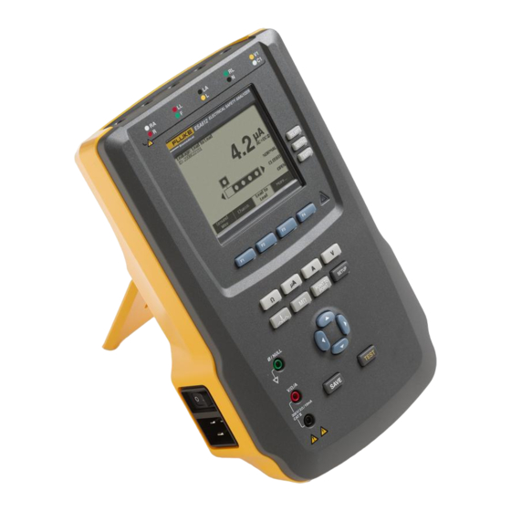
ESA612 Users Manual Table 2. Top-Panel Controls and Connections Instrument Familiarization Item Name Description Figure 1 and Table 2 describes the front-panel controls and connections of the Analyzer. Controls the configuration of the equipment outlet. Opens Equipment Outlet and closes the neutral and... - Page 21 Electrical Safety Analyzer Instrument Familiarization Item Name Description Test Button Initiates selected tests. Saves the measurement or Save Button ECG waveform to memory. Test lead connectors. Input Jacks Connection for zeroing test Nulling Jack lead resistance. Keys F1 through F4 are used to select from a number of Function Softkeys selections that appear in the...
- Page 22 ESA612 Users Manual Figure 2 and Table 3 describe the side and top-panel connections of the Analyzer. fis110.png Figure 2. Side and Top-Panel Connections...
- Page 23 Electrical Safety Analyzer Instrument Familiarization Table 3. Side and Top-Panel Connections Item Name Description Equipment outlet, specific to the version of the Analyzer, which provides a DUT Equipment Outlet connection. USB Device Port Digital connection for controlling the Analyzer from a PC or instrument controller.
-
Page 24: How To Hold The Product
ESA612 Users Manual How to Hold the Product Connecting to Line Power When you move the Analyzer, use the handle in the Warning bottom case to hold it. See Figure 3. To avoid shock hazard and for proper Analyzer operation, connect the factory... -
Page 25: Connecting A Dut To The Analyzer
Electrical Safety Analyzer Connecting a DUT to the Analyzer Connecting a DUT to the Analyzer A Device Under Test (DUT) can be connected in a number of different ways depending on the device and the number of connections needed for a full electrical safety test. - Page 26 ESA612 Users Manual fis113.png Figure 5. DUT Connections to the Analyzer...
-
Page 27: Accessing The Analyzer's Functions
Electrical Safety Analyzer Accessing the Analyzer’s Functions These icons indicate the use of and to select an During the self-test, the Analyzer checks its ac mains applied part. input for proper polarity, ground integrity and voltage level. The high voltage indicator illuminates briefly during the self test. -
Page 28: Setting Up The Analyzer
ESA612 Users Manual Figure 6 shows polarity is settable between normal, Note reversed, and off. Neutral is also settable to closed or See the Using Memory section later in this open. Earth condition is not displayed, which indicates it manual for a description of how to enter a test can not be changed. -
Page 29: Setting The Display Contrast
Electrical Safety Analyzer Setting Up the Analyzer To set the polarity delay: To set the GFCI current limit: From the Setup menu, push or until the From the Setup menu, press the softkey labeled Polarity Delay variable is highlighted. Instrument to reveal the instrument setup selections. -
Page 30: Setting Up The Beeper
ESA612 Users Manual Setting up the Beeper Setting the GFCI Limit To enable or disable the beeper: To set the GFCI current limit: From the setup menu, press the softkey labeled From the setup menu, press the softkey labeled More twice to set F2 to the beeper on/off function. -
Page 31: Performing Electrical Safety Tests
Electrical Safety Analyzer Performing Electrical Safety Tests Performing Electrical Safety Tests Performing Mains Voltage Testing The Mains Voltage test measures the voltage on the The Analyzer is designed to perform a number of different mains input through three separate measurements. To electrical and performance tests on biomedical access the Mains Voltage test, press . -
Page 32: Performing A Ground Wire (Protective Earth) Resistance Test
ESA612 Users Manual connect it to the other end of the test lead, place the Performing a Ground Wire (Protective Earth) null post adapter in the ∅/Null jack, and clamp the Resistance Test alligator clip to the null post adapter. - Page 33 Electrical Safety Analyzer Performing Electrical Safety Tests Warning To avoid electric shock, remove the null post adapter from the ∅/Null jack after a test lead zero is performed. The ∅/Null jack becomes potentially hazardous during some of the test conditions.
- Page 34 ESA612 Users Manual fis112.png Figure 10. Ground Wire (Protective Earth) Resistance Measurement Connections...
- Page 35 Electrical Safety Analyzer Performing Electrical Safety Tests Table 4. Schematic Abbreviations Abbreviation Meaning Measuring Device (ESA612 Analyzer) Functional Earth Protective Earth Mains Mains Voltage Supply Live Conductor Neutral Conductor Device Under Test DUT_L1 Device Under Test Live conductor DUT_L2 Device Under Test neutral conductor...
- Page 36 ESA612 Users Manual faw26.png Figure 11. Ground Wire (Protective Earth) Resistance Measurement Schematic...
-
Page 37: Performing An Insulation Resistance Test
Electrical Safety Analyzer Performing Electrical Safety Tests Performing an Insulation Resistance Test labeled More. The softkey labeled Back will move the menu back up to the top-level insulation resistance test Note menu. A reading of OR is used to indicate “Over Range”, a resistance reading which exceeds the maximum resistance value measurable on the Analyzer. - Page 38 ESA612 Users Manual faw17.png Figure 13. Mains to Protective-Earth Insulation Resistance Test Schematic...
- Page 39 Electrical Safety Analyzer Performing Electrical Safety Tests faw18.png Figure 14. Applied Parts to Protective-Earth Insulation Test Schematic...
- Page 40 ESA612 Users Manual faw19.png Figure 15. Mains to Applied Parts Insulation Test Schematic...
- Page 41 Electrical Safety Analyzer Performing Electrical Safety Tests faw20.png Figure 16. Mains to Non-Earth Accessible Conductive Points Schematic...
- Page 42 ESA612 Users Manual faw21.png Figure 17. Applied Parts to Non-Earth Conductive Points Schematic...
-
Page 43: Performing A Current Consumption Test
Electrical Safety Analyzer Performing Electrical Safety Tests Which leakage tests are available depends on which Performing a Current Consumption Test standard is selected. See the Selecting the Test Standard To measure the current consumed by the DUT, press section earlier in this manual to change the standard the . -
Page 44: Measuring Earth Leakage Current
ESA612 Users Manual Measuring Earth Leakage Current Note The Ground Wire (Earth) Leakage test is available for AAMI, 60601, and not IEC 62353. To measure the current flowing in the DUT’s protective earth circuit, press the softkey labeled Ground Wire (pending the standard) from the leakage current main menu. - Page 45 Electrical Safety Analyzer Performing Electrical Safety Tests The following outlet conditions apply when performing this test: • Normal Polarity Normal Polarity, Open Neutral • • Reversed Polarity Reversed Polarity, Open Neutral • IEC60601-1 specifies that the applied parts should be connected for this measurement.
- Page 46 ESA612 Users Manual faw27.png Figure 19. Earth Leakage Current Test Schematic Note Ground wire leakage is the same schematic without the Applied Parts switch.
-
Page 47: Performing A Chassis (Enclosure) Leakage Test
Electrical Safety Analyzer Performing Electrical Safety Tests Performing a Chassis (Enclosure) Leakage Test The following outlet conditions apply when performing this test: Note Normal Polarity • The Chassis (Enclosure) Leakage test is only • Normal Polarity, Open Earth available for the IEC60601 or ANSI/AAMI ES1 1993 standard selections. - Page 48 ESA612 Users Manual faw28.png Figure 20. Enclosure Leakage Current Test Schematic Note Chassis leakage is the same schematic without the Applied Parts switch.
-
Page 49: Performing A Lead-To-Ground (Patient) Leakage Test
Electrical Safety Analyzer Performing Electrical Safety Tests Performing a Lead-to-Ground (Patient) Leakage The Lead-to-Ground Leakage test can be performed with a number of fault conditions on the test receptacle. Press Test to switch the test receptacle between Normal, Off, Note Reverse, and Off. - Page 50 ESA612 Users Manual gtv29.png Figure 21. Lead-to-Ground (Patient) Leakage Current Test Schematic...
-
Page 51: Performing Lead-To-Lead (Patient Auxiliary) Leakage Tests
Electrical Safety Analyzer Performing Electrical Safety Tests After each post is isolated individually, the Lead-to-Lead Performing Lead-to-Lead (Patient Auxiliary) Leakage (Patient Auxiliary) Leakage test measures current of three Tests different combinations of posts tied together: RA/R and Note LL/F, RA/R and LA/L, or LL/F and LA/L. The Lead-to-Lead (Patient Auxiliary) leakage test is available when the IEC60601 or ANSI/AAMI ES1-1993 standard is selected. - Page 52 ESA612 Users Manual gtv30.png Figure 23. Lead-to-Lead (Patient Auxiliary) Leakage Current Test Schematic...
-
Page 53: Performing A Lead Isolation (Mains On Applied Part) Leakage Test
Electrical Safety Analyzer Performing Electrical Safety Tests The following outlet conditions apply when performing this Press . test: Press the soft key labeled More. Normal Polarity • Select the desired applied part groupings using • Normal Polarity, Open Neutral and . Normal Polarity, Open Earth •... - Page 54 ESA612 Users Manual The following outlet conditions apply when performing this test: Normal Polarity • • Reverse Polarity Note If there are more than five applied parts to connect to the Analyzer, see Using the 1-to-10 Adapter later in this manual.
- Page 55 Electrical Safety Analyzer Performing Electrical Safety Tests DEVICE UNDER TEST Mains DUT_L1 APPLIED PART Mains DUT_L2 DUT_PE CONDUCTIVE PART TEST LEAD LEAD SELECT RELAY* LEAD GND MAP (ISOLATION) SELECT RELAY* TRANSFORMER (REMOTE ONLY) *Leads not selected are open. gtv31.png Figure 24. Lead Isolation (Mains On Applied Parts) Leakage Test Schematic...
-
Page 56: Performing An Alternative Equipment Leakage Test
ESA612 Users Manual The following outlet conditions apply when performing this Performing an Alternative Equipment Leakage test: Test Closed Earth • Note • Open Earth The alternative equipment leakage test is available when the EN62353 standard is Note selected. If there are more than five applied parts to... -
Page 57: Performing An Alternative Applied Part Leakage Test
Electrical Safety Analyzer Performing Electrical Safety Tests Performing an Alternative Applied Part Leakage Test Note The Alternative applied part leakage test is available when the EN62353 standard is selected. During the Alternative Applied Part Leakage test, the test voltage is applied between short-circuited applied parts of a single function and the short-circuited equipment outlet mains live, neutral, equipment outlet earth, and exposed conductive surface on the housing. - Page 58 ESA612 Users Manual faw22.png Figure 25. Alternative Equipment Leakage Current Test Schematic...
-
Page 59: Performing A Direct Equipment Leakage Test
Electrical Safety Analyzer Performing Electrical Safety Tests To perform an alternative applied part leakage test: Performing a Direct Equipment Leakage Test Press . Note Press the soft key labeled More. The Direct Equipment Leakage test is available when the EN62353 standard is selected. Select the desired applied part groupings using ... - Page 60 ESA612 Users Manual The following outlet conditions apply when performing this test: Normal Polarity, Closed Earth • Normal Polarity, Open Earth • • Reversed Polarity, Closed Earth • Reversed Polarity, Open Earth Note If there are more than five applied parts to connect to the Analyzer, see Using the 1-to-10 Adapter later in this manual.
- Page 61 Electrical Safety Analyzer Performing Electrical Safety Tests gtv23.png Figure 26. Alternative Applied Part Leakage Test Schematic...
-
Page 62: Performing A Direct Applied Part Leakage Test
ESA612 Users Manual Performing a Direct Applied Part Leakage Test Press to apply the test voltage and read the current in the display. Note Press or to advance to the next group of applied The Direct Applied Part Leakage test is available parts, if applicable. - Page 63 Electrical Safety Analyzer Performing Electrical Safety Tests faw24.png Figure 27. Direct Equipment Leakage Test Schematic...
- Page 64 ESA612 Users Manual gtv25.png Figure 28. Direct Applied Parts Leakage Current Test Schematic...
-
Page 65: Performing A Differential Leakage Current Test
Electrical Safety Analyzer Performing Electrical Safety Tests Performing a Differential Leakage Current Test Note If there are more than five applied parts to Note connect to the Analyzer, see Using the 1-to-10 The Differential Leakage Current test is available Adapter later in this manual. when the EN62353 standard is selected. - Page 66 ESA612 Users Manual gtv32.png Figure 29. Differential Leakage Current Test Schematic...
-
Page 67: Using The 1-To-10 Adapter
Electrical Safety Analyzer Using the 1-to-10 Adapter Using the 1-to-10 Adapter The 1-to-10 Adapter, an optional accessory, is designed to increase the number of lead or applied parts connections to the Analyzer from five to 14. The adapter itself ties up to ten leads together into a single lead that is plugged into one of the input jacks of the Analyzer. - Page 68 ESA612 Users Manual fis120.png Figure 30. 1-to-10 Adapter Connections...
- Page 69 Electrical Safety Analyzer Using the 1-to-10 Adapter When performing an applied parts test using the AAMI/NFPA-99 standard, the normal connections of RA, LL, LA, and RL are made to their associated Analyzer input jacks. Four adapters from the Universal Snap to Banana Adapter set will be required for the first four connections.
- Page 70 ESA612 Users Manual fis121.png Figure 31. ECG Lead Connection with 1-to-10 Adapter...
-
Page 71: Making Point-To-Point Measurements
Electrical Safety Analyzer Making Point-To-Point Measurements Making Point-To-Point Measurements Place the probe tips across the unknown voltage and read the measurement in the Analyzer’s display. The Analyzer can make voltage, resistance, and low The Analyzer will measure up to 300 volts ac. current measurements through its Point-to-Point function. -
Page 72: Measuring Current
ESA612 Users Manual Measuring Current Note If the ECG monitor/interpreter has banana posts The Analyzer can make dc only, ac only, and ac+dc instead of snaps, use the optional universal snap current measurements up to 10 mA. To make a current to banana adapter to connect to the Analyzer. - Page 73 Electrical Safety Analyzer Simulating ECG Waveforms To select one of the predefined waveforms, press the softkey labeled Wave Form. A scroll box with next to it appears above the softkey label. Use or to scroll through the different waveforms. For all waveforms except VFIB and Triangle, the rate or frequency of the waveform is adjusted through the softkey labeled Frequency or Rate.
- Page 74 ESA612 Users Manual fis115.png Figure 34. ECG Monitor Connections...
-
Page 75: Using Memory
Electrical Safety Analyzer Using Memory Using Memory record. Press (enter save button) to store the Test Record ID. The non-volatile memory of the Analyzer will store up to 500 measurements or ECG information for each of 100 Use , , , and to enter the date of the Test different Test Records. -
Page 76: Viewing Memory Data
ESA612 Users Manual Viewing Memory Data Previously stored data for any Test Record is recalled to the screen through the setup menus. To recall data: Press . Press the softkey labeled More to reveal additional menu selections. Press the softkey labeled View Memory. -
Page 77: Deleting Data From Memory
Controlling the Analyzer Remotely Deleting Data from Memory To delete a Test Record and its associated data from Fluke Biomedical Ansur test automation software allows a memory: solutions-based approach to complete testing of the medical device under test (DUT). Ansur helps create Press . -
Page 78: Maintenance
Ansur. This has the benefit of using the same user interface for all analyzers and simulators supported by an Ansur plug-in. When a new Fluke Biomedical analyzer or simulator is purchased, simply update your existing Ansur software by installing a new plug-in. Each plug-in module works only with the options and capabilities needed for the instrument being tested. - Page 79 Remove the fuse door from the Analyzer by removing the case bottom label of the Analyzer. Table 6 lists the screw holding the fuse door with a #2 Phillips available fuses with Fluke Biomedical part numbers. head screwdriver and lifting the fuse door from the Analyzer.
-
Page 80: Cleaning The Analyzer
ESA612 Users Manual Cleaning the Analyzer Warning To avoid electric shock, do not clean the Analyzer plugged into mains or attached to a DUT. Caution Do not pour fluid onto the Analyzer surface; fluid seepage into the electrical circuitry may cause the Analyzer to fail. -
Page 81: Replaceable Parts
Electrical Safety Analyzer Replaceable Parts Replaceable Parts Table 6 lists the replaceable parts for the Analyzer. Table 6. Replaceable Parts Item Fluke Biomedical Part Number ESA612 Getting Started Manual 3334511 ESA612 Users Manual CD 3334509 USA (220V) 2238644 2238596 Australia... - Page 82 ESA612 Users Manual Table 6. Replaceable Parts (cont.) Item Fluke Biomedical Part Number Carrying Case 2248650 Null Post Adapter 3326842 Ansur, CD with demo version 2795488 5-to-5 Banana Jack to ECG (BJ2ECG) Adapter 3359538 Data Transfer Cable 1626219 T20A 250V Fuse (Time Lag), 1¼ in x ¼ in...
-
Page 83: Accessories
Table 7 lists the available accessories for the Analyzer. Table 7. Accessories Item Fluke Biomedical Part Number Test Leads with Retractable Sheath 1903307 Ground Pin Adapters 2242165 1-to-10 ECG Adapter 3392119 Universal Snap to Banana Adapter 2462072 Ansur ESA612 Plug-In License 3454829... -
Page 84: Specifications
ESA612 Users Manual Specifications Temperature Operating ............10 °C to 40 °C (50 °F to 104 °F) Storage ............... -20 °C to 60 °C (-4 °F to 140 °F) Humidity ..............10 % to 90 % non-condensing Altitude 115 V ac mains supply voltage ......5000 m 230 V ac mains supply voltage ...... -
Page 85: Detailed Specifications
Electrical Safety Analyzer Detailed Specifications Class A: Equipment is suitable for use in all establishments other than domestic and those directly connected to a low voltage power supply network which supplies buildings used for domestic purposes. There may be potential difficulties in ensuring electromagnetic compatibility in other environments, due to conducted and radiated disturbances. - Page 86 ESA612 Users Manual Leakage Current Modes* ..............AC+DC (True-rms) AC only DC only * Modes: AC+DC, AC only, and DC only available for all leakages with exception of MAP that are available in True-rms (shown as AC+DC) Patient Load Selection ........AAMI ES1-1993 Fig. 1 IEC 60601: Fig.
- Page 87 Electrical Safety Analyzer Detailed Specifications Differential leakage Ranges ..............75 to 199 µA 200 to 1999 µA 2.00 to 20.00 mA Accuracy.............. ±(10 % of reading + (2 counts or 20 µA, whichever is greater)) Insulation resistance Ranges ..............0.5 to 20.0 MΩ 20.0 to 100.0 MΩ...
Need help?
Do you have a question about the ESA612 and is the answer not in the manual?
Questions and answers