
Related Manuals for alphatronics UNii AT-100

Summary of Contents for alphatronics UNii AT-100
- Page 1 UNii Door controller Installation manual UNii Deur controller installatie handleiding English page 2 Nederlands pagina 21...
-
Page 2: Table Of Contents
Table of contents UNii door controller ............................. 4 Mounting ................................4 Connections ................................. 5 Connections ................................. 6 Power supply ................................ 6 Backup power supply ............................6 Protection against discharge ..........................6 Low battery voltage ............................6 230V mains connection ............................. 7 Jumpers ................................ - Page 3 AT-400P ................................21 Mounting steps ..............................21...
-
Page 4: Unii Door Controller
UNii door controller The UNii door controller can be connected to the RS-485 bus of the UNii control panel and is intended for access control of two doors with associated readers. The controller is available in two versions 12 and 24V and has an independent voltage and emergency power supply and is supplied in a metal housing. -
Page 5: Connections
Connections 1. Reader 1 - RTE and door position inputs 2. Reader 1 (Wiegand) connection 3. Reader 1 - LED and OC output 4. Reader 2 -RTE and door position inputs 5. Reader 2 (Wiegand) connection 6. Reader 2 -LED and OC output 7. -
Page 6: Connections
Connections 2 reader (Wiegand) inputs with power supply and connections for LED indication and buzzer. (Equipped with a polyfuse 100mA) 2 Request to Exit (RTE) inputs (1 per door). If this input is activated, the corresponding door control (relay) will be activated for the set time. 2 Door position inputs (1 per door). -
Page 7: 230V Mains Connection
230V mains connection A mains fuse with a value of 315 mA is included in the terminal block. The installation must be equipped with a double-pole switch / disconnector to make the mains connection completely voltage-free. The mains voltage is connected to the terminal block in the cabinet. The middle connection is the earth connection, and this connection is connected to the metal enclosure of the control panel. -
Page 8: General Specifications
Weight: 5200gr excluding battery. Control panel cabinet must be installed within the protected area. The maximum depth (thickness) of the battery is 100 mm. Manufacturer: Alphatronics BV Operating temperature: 0° C tot +40° C Storage temperature: -20° C tot +60° C Humidity: 85% relative humidity at 30°... -
Page 9: System Requirements
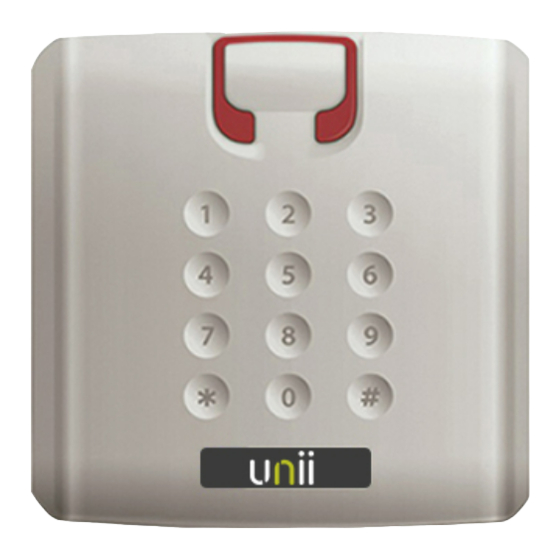
If the installation does not comply with Grade 1, 2 or 3, the labels MUST be removed or made clear in another way that the installation is non-compliant! The serial number must not be removed. AT-100 The AT-100 access reader is a DESFire EV2 access control reader for the UNii control panel. The AT-100 can be used for access control applications and/or arming and disarming of the UNii control panel. -
Page 10: Measurements
The rubber seal is a foam rubber pad that can be mounted between the access reader and the mounting surface to ensure a better protection from water and moisture getting into the back of the access reader. The rubber seal can also be used when mounting the access reader on an uneven surface like a brick wall. -
Page 11: Mounting Steps
Mounting steps Mount the access reader preferably on a flat surface. Drill two holes for mounting the backplate of the access reader on the preferred location. • The hole diameter should be 6mm for plugs in a brick wall and 3mm in wooden walls. Pull the cable through the backplate (and spacer or rubber seal, if applicable). -
Page 12: Connections And Indicators
Connections and indicators The AT-100 access reader contains the following indicators and connections:... -
Page 14: Connecting Card Reader Interface
Connecting Card Reader interface Label Interface Description Light Guide Multicolor RGB LED to display status Buzzer Multitoe buzzer for audio feedback Dip switch 3-pin DIP switch for RS-485 purpose (not used) 9-pin connector Connector to connect to Card Reader interface or Door controller AT-100 with pigtail Terminal... -
Page 15: System Requirements
AT-200P The AT-200P keypad access reader is a DESFire EV2 access control reader including keypad for the UNii control panel. The AT-100 can be used for access control applications and/or arming and disarming of the UNii control panel. System requirements The AT-200P keypad access reader can only be used on the UNii control panel and supports DESFire EV2 tags (art.code 008072 and 008074) and cards (008075). -
Page 16: Measurements
Measurements Location • Determine the location where the AT-200P keypad access reader should be installed. Please note that there is a maximum cable length of 100m between the keypad access reader and the card reader interface or Door controller. Keep a minimum distance of 20cm between AT-100 and AT-200P access readers. •... -
Page 17: Connections
Connections The AT-200P keypad access reader contains the following connections: Pin number Wiegand Not used Not used Ext Input 1 (LED) Power connedtion (5-16VDC) Technical specifications AT-100 / 200P AT-100 AT-200P Power supply 5-16 VDC 25mA 5-16 VDC 25mA Current drain 125mA@12VDC 175mA@12VDC Dimensions... -
Page 18: Connecting At-100 And At-200P To Card Reader Interface
Connecting AT-100 and AT-200P to Card Reader Interface Reader Interface controller Wiegand Clock/Data Wiegand Clock/Data TAMP Tamper Contact Buzzer driver Led Driver (Green) Led Driver (Red) 12 VDC Dipswitch instelling Card Reader Interface TXD/RXD Debug/Flashing Auto addressing TAMP Bridge tamper casing PROG Debug/Flashing Address 1... -
Page 19: Connecting At-100 And At-200P To Door Controller
Connecting AT-100 and AT-200P to Door controller Reader Door controller Wiegand Clock/Data Wiegand Clock/Data Tamp Tamper contact Buzzer driver Led Driver (Green) Led Driver (Red) 12 VDC Rotary switch Jumpers Rotary setting TXD/RXD Debug/Flashing Auto addressing TAMP Bridge tamper casing Fixed addressing PROG Debug/Flashing... -
Page 20: Mounting Steps
AT-300 Mounting steps Mount the reader on an even surface. Connect the wires to the power supply, Wiegand controller etc. Right after applying the voltage all 3 LED’s lights and the buzzer beeps. Right after the yellow LED is lit and the buzzer is silent. 9 –... - Page 21 AT-400P Mounting steps Mount the reader on an even surface. Connect the wires to the power supply, Wiegand controller etc. Cable Color Function VDC: 9 - 24 VDC / -5% +0% (should never exceed 24VDC) Black GND: 0V Yellow White Wiegand D1: Clock.
- Page 22 UNii Door controller Installation manual UNii Deur controller installatie handleiding English page 2 Nederlands pagina 21...
- Page 23 Inhoudsopgave UNii deur controller ............................25 Montage ................................25 Aansluitingen ..............................26 Connecties ................................27 Voeding................................27 Noodstroom voeding ............................27 Beveiliging tegen ontladen..........................27 Lage accuspanning ............................27 230V voedingsspanning ..........................28 Jumpers ................................28 Algemene specificaties ............................ 29 Zekeringen ................................
- Page 24 Aansluitingen ..............................42...
-
Page 25: Unii Deur Controller
UNii deur controller De UNii deur controller kan aangesloten worden aan de RS-485 bus van het UNii centrale en is bedoeld om de toegang van twee deuren met geassocieerde kaartlezers te bedienen. De deur controller is beschikbaar in twee varianten, een 12V en 24V variant en heeft een zelfstandige volt en nood voeding en is geleverd in een metalen behuizing. -
Page 26: Aansluitingen
Aansluitingen 1. Lezer 1 – RTE en deurstand 2. Lezer 1 - (Wiegand) aansluiting 3. Lezer 1 – LED en OC-uitgang 4. Lezer 2 – RTE en deurstand 5. Lezer 2 – (Wiegand) aansluiting 6. Lezer 2 – LED en OC-uitgang 7. -
Page 27: Connecties
Connecties 2 lezer (Wiegand) aansluitingen met voeding en aansluitingen voor LED-indicaties en buzzer. (Voorzien van polyfuse zekering 100mA) 2 Request to Exit (RTE) ingangen (1 per deur). Als deze ingang is geactiveerd zal de bijbehorende deur uitgang (relais) geactiveerd worden voor de ingestelde tijd. 2 deur positie ingangen (1 per deur). -
Page 28: 230V Voedingsspanning
230V voedingsspanning Een glaszekering 315mA is aanwezig in de kroosteen met zekerhouder van de binnenkomende 230VAC netspanning. De installatie moet worden uitgerust met een dubbelpolige elektra automaat om de netspanning volledig spanningsloos te maken. De glaszekering is geplaatst tussen de L lijn van de kroonsteen. De middelste aansluiting is de aarde draad, deze is verbonden met de metalen behuizing van de Deur controller. -
Page 29: Algemene Specificaties
Gewicht: 5200gr exclusief batterij. Deur Controller moet worden geïnstalleerd binnen het beveiligd gebied. De maximale diepte (dikheid) van de batterij is 100 mm. Fabrikant: Alphatronics BV Bedrijf temperatuur: 0° C tot +40° C Opslag temperatuur: -20° C tot +60° C Vochtigheid: 85% relatieve vochtigheid bij 30°... -
Page 30: Systeemeisen
AT-100 De AT-100 deurlezer is een DESFire EV2 toegangslezer voor de UNii centrale. De AT-100 kan worden gebruikt voor toegangscontrole en/of het in- en uitschakelen van de UNii centrale. Systeemeisen De AT-100 toegangslezer kan alleen gebruikt worden op de UNii centrale en leest DESFire EV2 tags (art. -
Page 31: Afmetingen
Afmetingen Locatie Bepaal de locatie waar de AT-100 kaart lezer moet worden geïnstalleerd. Hou er rekening mee dat er een maximale kabellengte is van 100m tussen de toegangslezer en de kaartlezer interface of deur controller. Houd een maximale afstand van 20cm tussen toegangslezers. De AT-100 bij voorkeur niet installeren op een metaal ondergrond, als dit niet anders kan gebruik dan een afstandplaat om optimale leesafstand te behouden. -
Page 32: Montage Stappen
Montage stappen Monteer de toegangslezer bij voorkeur op een vlak ondergrond. Teken de 2 montagegaten af mbv de achterplaat van de toegangslezer en boor de 2 gaten. De diameter van de gaten is 6mm voor pluggen in een stenen muur en 3mm in houten muren. Haal de kabel door de achterplaat (en afstandplaat of rubberen pad indien van toepassing). -
Page 33: Aansluitingen En Indicatoren
Aansluitingen en indicatoren De AT-100 heeft de volgende aansluitingen en indicatoren... -
Page 34: Aansluitingen
Aansluitingen Label Interface Beschrijving Multikleur Led om status aan te geven Buzzer Multitoon buzzer om status aan te geven Dip switch 3-pin DIP switch voor RS-485 instelling (niet gebruikt) 9-polige connector Connector voor kabel naar kaartlezer interface of deur controller AT-100 met pigtail Aansluitingen Beschrijving... -
Page 35: Systeemeisen
AT-200P De AT-200P keypad toegangslezer is een DESFire EV2 deurlezer voor het UNii centrale. De AT-200 kan worden gebruikt voor toegangscontrole applicaties en/of in-en uitschakelen van de UNii centrale. Systeemeisen De AT-200P toegangslezer kan alleen gebruikt worden op de UNii centrale en leest DESFire EV2 tags (art. -
Page 36: Afmetingen
Afmetingen Locatie Bepaal de locatie waar de AT-200P keypad toegangslezer moet worden geïnstalleerd. Hou er rekening mee dat er een maximale kabellengte is van 100m tussen de toegangslezer en de kaartlezer interface of deurcontroller. Houd een maximale afstand van 20cm tussen toegangslezers. De AT-200P bij voorkeur niet installeren op een metaal ondergrond, als dit noodzakelijk is gebruik dan een afstandplaat om optimale leesafstand te behouden. -
Page 37: Aansluitingen
Aansluitingen De AT-200P keypad toegangslezer heeft de volgende aansluitingen: Klemnummer Wiegand Niet gebruikt Niet gebruikt Ext Ingang 1 (LED) Voeding (5-16VDC) Technische specificities AT-100 / 200P AT-100 AT-200P Voeding: 5-16 VDC 25mA 5-16 VDC 25mA Afvoer: 125mA@12VDC 175mA@12VDC Afmetingen: 142 x 45 x 22mm 80 x 80 x 19mm IP rating: IP54/IP64... -
Page 38: At-100 En At-200P Op Kaartlezer Interface Aansluiten
AT-100 en AT-200P op kaartlezer interface aansluiten Toegangslezer Kaartlezer interface Wiegand Clock/Data Wiegand Clock/Data TAMP Sabotage Contact Buzzer aansturing Led aansturing (Groen) Led aansturing (Rood) 12 VDC... - Page 39 Dipswitch instelling Card Reader Interface TXD/RXD Debug/Flashing TAMP Overbrug sabotage Auto addressing PROG Debug/Flashing Address 1 RESET Reset module Address 2 Debug/Flashing Address 3 Address 4 Address 5 Address 6 Address 7 Address 8 Address 9 Address 10 Address 11 Address 12 Address 13 Address 14...
-
Page 40: At-100 En At-200P Op Deur Controller Aansluiten
AT-100 en AT-200P op Deur controller aansluiten Toegangslezer Deur controller Wiegand Clock/Data Wiegand Clock/Data Sabotage contact Tamp Buzzer aansturing Led aansturing (Groen) Led aansturing (Rood) 12 VDC Rotary switch Jumpers Rotary setting TXD/RXD Debug/Flashing Auto addressing TAMP Overbrug sabotage Fixed addressing PROG Debug/Flashing RESET... -
Page 41: Aansluitingen
AT-300 Aansluitingen Sluit de lezer aan op een gelijke ondergrond. Sluit de bedrading aan op de voeding, Wiegand Controller etc. Direct na het inschakelen van de spanning lichten alle 3 LED's op en piept de buzzer. Vervolgens gaat de gele LED branden en is de buzzer stil. - Page 42 AT-400P Aansluitingen Sluit de lezer aan op een gelijke ondergrond. Sluit de bedrading aan op de voeding, Wiegand Controller etc. Draad kleur Functie VDC: 9 - 24 VDC / -5% +0% (should never exceed 24VDC) Black GND: 0V Yellow White Wiegand D1: Clock.
- Page 43 WEEE-declaration This Alphatronics product is manufactured with the most modern technology and consists of high-quality components. Most of the components used can be recycled. The symbol means that this product should be recycled separately and not put in the normal waste bin together with normal household waste.
Need help?
Do you have a question about the UNii AT-100 and is the answer not in the manual?
Questions and answers