Table of Contents
Advertisement
Quick Links
Advertisement
Table of Contents

Subscribe to Our Youtube Channel
Related Manuals for Takachiho Sangyo GUIDER 6 PLUS


Summary of Contents for Takachiho Sangyo GUIDER 6 PLUS
- Page 1 Boring Head Locating System Operation Manual TAKACHIHO SANGYO CO., LTD...
- Page 2 For your safety ■Please read manual carefully before attempting to operate and use only as directed. ■After reading, please keep manual where it is easy to find. ■For the purposes of quality control and product improvement, we have placed control numbers on some units. We appreciate your understanding. Danger ・Do not place batteries near an open flame or attempt to take apart or modify them.
-
Page 3: Table Of Contents
Table of Contents ・・・・・・・・・・・・・ 1. Product Summary ・・・・・・・・・・・・・ 2. Product Specifications ・・・・・・・・・・・・・ 1) Locator ・・・・・・・・・・・・・ 2) Monitor ・・・・・・・・・・・・・ 3) Probe ・・・・・・・・・・・・・ 3. List of Part Names ・・・・・・・・・・・・・ 3-1. Locator ・・・・・・・・・・・・・ 1) List of part names ・・・・・・・・・・・・・ 2) Replacing the batteries ・・・・・・・・・・・・・... -
Page 4: Product Summary
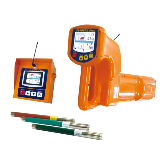
1. Product Summary This product measures the position, angle and depth of the drill head for Horizontal Directional Drilling. The product is composed of a locator, a monitor and a probe (transmitter). Monitor Locator Drill Unit Electromagnetic (EM) field Boring Head (drill) Component Explanation Locator... -
Page 5: Product Specifications
2. Product Specifications 1) Locator Item Standard Receiving frequency 38 kHz, 14.4 kHz, 9.5 kHz Power source 6 Alkaline “C” batteries Battery life 12 hours (at 25°C, using alkaline batteries) Power saving function Power turns off after no signal for 10 minutes or more Operating temp. -
Page 6: Monitor
2) Monitor Item Standard Power source 4 Alkaline “C” batteries Battery life 12 hours (at 20 C using alkaline batteries) Power saving function Power turns off after no signal for 5 minutes or more Operating temp. range -20 ~ 60°C Display screen Color LCD (with backlight) Probe information, lateral position (right and left),... - Page 7 3) Probe General Specifications Item Standard 2 Alkaline “C” batteries Power source 10 hours or more (at 25°C, using alkaline batteries) Battery life Automatically turns off after 10 minutes without rotating Power saving function -20 ~ 60°C Operating temp. range Displayed in degrees ↑50.0°~ ↓50.0°...
-
Page 8: List Of Part Names
3. List of Part Names 3-1. Locator 1) List of part names Control panel Waterproof Buzzer Battery Collapsible antenna compartment Antenna that receives the signal from the probe is contained here 2) Replacing the batteries Ⅰ) Turn the knob on the lid of the battery compartment on the back of the receiver. counterclockwise to open it. -
Page 9: Explanation Of Control Panel
3) Explanation of Control Panel Line for aligning with yaw angle Ⅲ) Locator battery indicator Ⅰ) Wireless channel Ⅳ) Position and depth of probe Ⅱ) Digital Ⅴ) Posture info level of probe POWER MODE ON/OFF switch Button for various settings LOCATE (▲) L/R (▼) ·... -
Page 10: Monitor
3-2. Monitor 1) List of part names Collapsible antenna Rear Hatch BNC Connector Control Panel Latch 2) Replacing the batteries Ⅰ) Release the latch on the side of the monitor to open the rear hatch. Ⅱ) Put in 4 “C” type alkaline batteries. Insert the batteries in the direction displayed on the label in the battery case. -
Page 11: Explanation Of Control Panel
4) Explanation of control panel Ⅱ) Monitor battery Ⅰ) Wireless indicator channel Ⅲ) Probe location and depth RX ERROR Ⅴ) Probe Ⅳ) Reception posture condition information c) MODE a) POWER b) CH. SELECT(▲▼) Outline of LCD display Ⅰ) Wireless channel Displays wireless channel used between locator and monitor Ⅱ) Monitor battery indicator Displays the remaining battery power of the monitor itself... -
Page 12: Probe
3-3. Probe 1) List of part names Probe body To help distinguish between products, each probe is colored differently according to frequency Probe Head Contains a slot to that determines the Battery cap position within the boring head 2) Replacing the batteries Ⅰ) Remove the battery cap from the rear of the probe. -
Page 13: Operating The Locator
4. Operating the Locator 1) Settings Before use, it is necessary to adjust settings and perform depth calibration. Pressing the MODE button from the measurement screen will bring up the settings screen. (indicated in the diagram below) Navigate the menu by pressing the locate (▲) and L/R (▼) button. (The current selected setting will appear in red) To make your selection, Press the MODE button. - Page 14 Ⅱ) Selecting a wireless channel Set the locator and the monitor to the same wireless channel. ※The minus mark [-] as indicated in the figure below means that the transmission is off. In the case of poor reception quality or interference, please change to a different channel. b) Toggle between channels c) Press MODE again a) Navigate to the wireless icon...
- Page 15 2) Selecting the measurement mode There are two scanning methods available: One for measuring the lateral position (L/R) of the drill from a long distance (long distance mode), and one for measuring the position from directly above the drill (Near distance mode). There are two settings to switch between scanning methods: AUTO mode switches automatically, and MANU mode allows the user to switch between methods manually.
-
Page 16: Depth Correction (Calibration)
3) Depth correction (Calibration) Ⅰ) Set-up From a position of 3m from the boring head, place the locator as indicated in the diagram below. a) Insert the probe inside the boring head b) Place the boring head so that the axis of the locator and the axis of the boring head are parallel to each other Ⅱ) Starting calibration Turn the locator ON and begin depth calibration. - Page 17 4) Measuring noise As the levels of outside noise varies between job sites, the range of transmission will change. For this reason it is useful to take a reading of the noise level of the jobsite before beginning. Ⅰ) Perform calibration as described in section 3) - Depth Correction (calibration) Ⅱ) Remove the batteries from the probe so that there is no signal coming from it.
-
Page 18: Measuring Position
5) Measuring position There are two methods for measuring location, as indicated in the diagram below. The way of measuring varies based on if the unit is in AUTO mode or MANU mode. a) Near distance mode b) Long distance mode (L/R position) AUTO AUTO 9999... - Page 19 Ⅱ) For MANU mode (Manually change between methods) a) Pressing the LOCATE button (▲) will enter near distance mode. Conduct scan as indicated in the diagram below (Side view). Behind the probe In front of the probe Drilling direction Depth mark Inter- Outside...
- Page 20 6) Near distance mode (Detailed explanation) Ⅰ) Direction of locator In near distance mode ensure that the locator is facing in the same direction as the drill is moving in. NOTE: If locator is facing the opposite direction, position errors related to pitch angle cannot be corrected properly.
- Page 21 Ⅴ) Adjusting sensitivity When sensitivity is too low, or display shows 9999, press the LOCATE (▲) button. Sensitivity will be adjusted automatically. ※When adjusting sensitivity, displayed value is relative value of 9000. Sensitivity is too low 7000 9000 Sensitivity is too high After 9999 adjustment...
- Page 22 Call & Contact TAKACHIHO SANGYO CO., LTD. Tokyo office 32-8, 5-Chome, Shiba, Minato-Ku, Tokyo 108-0014 TEL 81-3-3453-4778 Head office & Factory in Nagoya, Japan 2018.8 836-082...
Need help?
Do you have a question about the GUIDER 6 PLUS and is the answer not in the manual?
Questions and answers