
Related Manuals for Ideal Clima KERS 25


Summary of Contents for Ideal Clima KERS 25
- Page 1 HIGH EFFICIENCY SINGLE-ROOM HEAT RECOVERY UNITS KERS 25 WITH REMOTE CONTROL USER AND INSTALLER MANUAL...
-
Page 2: Table Of Contents
BEFORE USING THE UNIT, READ THIS MANUAL CAREFULLY SUMMARY SUMMARY ................................ 2 PREMISE ..............................3 RESPONSIBILITY ................................3 SERVICE RULES ................................. 4 INTERVENTIONS AND MAINTENANCE ..........................5 INTENDED USE ................................. 5 GENERAL SAFETY RULES ..............................5 PRODUCT DESCRIPTION ..........................6 STRUCTURE AND OPERATION ............................ -
Page 3: Premise
1 PREMISE This manual indicates the intended use of the unit and provides instructions for transporting, installing, mounting, adjusting and using the unit. Provides information for maintenance interventions, spare parts ordering, residual risks and staff training. The user and maintenance manual must be read and used as follows: Each operator and personnel assigned to use and maintenance of the unit must read this manual completely and with the utmost attention. -
Page 4: Service Rules
- modifications made to the unit and safety devices without the prior written authorization of the manufacturer; - attempts at repairs carried out on their own account or by unauthorized technicians; - lack of periodic and constant maintenance interventions or use of non-original spare parts. In any case, if the user attributes the accident to a defect of the unit, he must demonstrate that the damage occurred was a main and direct consequence of this "defect". -
Page 5: Interventions And Maintenance
INTERVENTIONS AND MAINTENANCE The user manual can never replace an adequate user experience; for some particularly demanding maintenance operations, this manual constitutes a reminder of the main activities to be carried out for operators with specific knowledge acquired, for example, by attending training courses at the manufacturer. Read the following tips carefully: Constant and careful preventive maintenance always guarantees the high operational safety of the unit. -
Page 6: Product Description
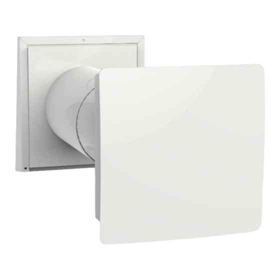
The exposed installation is aesthetically pleasing thanks to the elegant external covers. KERS is designed to be mounted in external walls with thickness from 300 mm to 570 mm on KERS 25. Special extensions allow to overcome greater thicknesses (see paragraph 9.5). -
Page 7: Operational Limits
KERS can work in three different modes: Ventilation: the unit works continuously in extraction. Injection: the unit operates continuously in injection. Heat recovery: the unit operates alternately in two phases of 65 seconds each: 2.1.1 Phase 1 - stale hot air is extracted from the room. As it flows through the ceramic heat exchanger, it heats it. -
Page 8: Operation Of Several Appliances Connected To Each One
3 OPERATION OF SEVERAL APPLIANCES CONNECTED TO EACH ONE When several KERS recovery units are installed in a single room, it is necessary to synchronize their operation so as not to put the environment under pressure or vacuum. The devices must be connected in series with each other (see chapter: electrical connections), so that when half of them work in extraction (phase 1), the other half works in supply (phase 2). - Page 9 If the site conditions require it, it is allowed to remove the Schuko plug supplied with the machine and its cable up to the terminals of the appliance, in compliance with the L / N / Earth connections, without thereby voiding the product warranty. 4.2.2 WIRING DIAGRAM FOR SERIES CONNECTION OF SEVERAL KERS (max.
-
Page 10: Buttons And Remote Control For Management Of The Unit
Internal view of the CN7 terminal board, side on which one must operate to move the jumper. 5 BUTTONS AND REMOTE CONTROL FOR MANAGEMENT OF THE UNIT The unit can be controlled with buttons located on the fan casing or with a remote control. The buttons allow you to activate second and third speeds and to set three of the four possible ventilation modes. -
Page 11: Remote Controller
To use the remote control, put the switches in the middle position. REMOTE CONTROLLER The remote control works only if the buttons on board are both in an intermediate position. The operating distance of the remote control can be affected by the environment in which it operates. Possible operations with the remote control: "ON-OFF"... -
Page 12: Technical Data
6 TECHNICAL DATA MAIN FEATURES Heat Recovery Description Unit Kers 25 with remote Code VRKS25 Air flow at maximum speed mc / h Air exchange mc / h Efficiency of ceramic recuperator up to 90 Thermal power recovered in winter... -
Page 13: Energy Label
ENERGY LABEL Brand Ideal Clima Model u.m. VRKS25 kWh/(m Cold Warm Specific Energy Consumption (SEC), Type of ventilation Bidirectional Starting type Multiple Speeds Type of heat recovery Regenerative Efficiency t. 13°C [ t] [ t] Maximum flow m Power consumption 5.32... -
Page 14: Dimensional Drawings
DIMENSIONAL DRAWINGS 7 AFTER SALES TROUBLESHOOTING The following pages list the most common causes that can cause the unit to block, or at least to malfunction. The division is made on the basis of easily identifiable symptoms. ANOMALY ANALYSIS OF POSSIBLE CAUSES CORRECTIVE ACTIONS Check for its presence on the power supply No power supply to the unit. -
Page 15: Routine Maintenance
ROUTINE MAINTENANCE Disconnect the unit from the mains before any maintenance operation. Proceed as follows: Remove the front panel. Pull to remove the fan unit Clean the fan blades. Clean the fan with a soft brush or vacuum cleaner. Do not use water, abrasive solvents or sharp objects. -
Page 16: Exploded View
WALL MOUNTING 9.4.1 Hole preparation Prepare a through hole in the wall with a diameter of 110 mm for KERS 25, inclined outwards by no more than 2°. 9.4.2 Telescopic duct insertion When several KERS recovery units are installed in series with each other (see specific chapter), it is necessary to provide passages for the connection cables between one KERS and the other, as well as for the power supply cable. - Page 17 Please note : Do not tighten the fixing screws, in order not to deform the plastic material support. This could make the fan noisy KERS 25 recovery unit u.m. VRKS25 Align the telescopic duct flush with the mounting plate and fill the gaps between the wall and the telescopic duct with foam sealing (polyurethane).
-
Page 18: Installation From Inside Using Flexible Grids
10 INSTALLATION FROM INSIDE USING FLEXIBLE GRIDS For installation of grids on inaccessible external walls, special flexible grids are available for Kers (optional), which can be installed from the inside. The grids for Kers 25 are as follows: CODE DESCRIPTION... -
Page 19: Extension Of The Duct For Thick Walls
If the wall thickness is greater than the maximum extensibility of the duct supplied with the appliance, it is possible to use the Kers telescopic extension accessory (code VPKT03 for Kers 25 and VPKT04 for Kers 50), which increases its length up to a further 80 cm. -
Page 20: Note
13 NOTE ........................................................................................................................................................................................................................................................................................................................................................................................................................................................................................................................................................................................................................................................................................................................................................................................................................................................................................................................................................................................................................................................................................ - Page 21 ...............................................................................................................................................................................................................................................................................................................................................................................................................................................................................................................................................................................................................................................................................................................................................................................................................................................................................................................................................................................................................................................................................................................................................................................................
-
Page 22: Warranty Conditions
14 WARRANTY CONDITIONS The guarantee of this product is governed by the Ideal Clima general conditions of sale (version 3.0) of which we report the part relating to the guarantee: Ideal Clima guarantees its products against manufacturing faults or defects, with the express exclusion of any defect or fact inherent in the installation, operation and maintenance of the product.