
Related Manuals for Comat Releco BoxX 2 Series


Summary of Contents for Comat Releco BoxX 2 Series
- Page 1 ComatReleco PLC + HMI BoxX 2 User Manual BoxX 2 series PLC is an upgraded version of BoxX series PLC. Before you use the product, please kindly read the manual carefully so as to ensure proper use of the product.
-
Page 2: Important Information
Important information ComatReleco reserves the right to alter, correct, and/or improve the technical documentation and the products described in the technical doc- umentation at its own discretion and without giving prior notice, insofar as this is reasonable for the user. The same applies to any technical changes that serve the purpose of technical progress. -
Page 3: Table Of Contents
Tabel of contents Important information ..................................2 Copyright .......................................2 Disclaimer ......................................2 Introduction ....................................4 Structure of BoxX 2 ..................................4 Specifications and models ................................4 BoxX 2 Features .....................................5 Installation and wiring .................................6 Installation .....................................6 2.1.1 Methods ......................................6 2.1.2 Dimensions (unit:mm) ..................................7 Wiring of BoxX 2 .....................................7 2.2.1 Connection of power supply ................................8 2.2.2... -
Page 4: Introduction
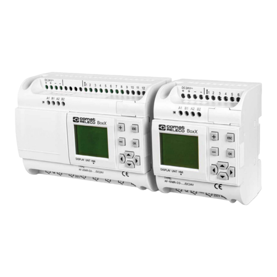
Introduction BoxX 2 series PLC is an upgraded version of old BoxX PLC, which is programmed by the use of a Function Block Diagram. The programming of BoxX 2 is simpler and easier to learn than that of a conventional PLC, which uses ladder diagrams and associated instructions. In the design concept of BoxX 2 series products, it adds power indicator, comes with 2-way 485 communication interface, supports standard MODBUS RTU protocol and can modify parameters and other functions through the LCD panel, which greatly reduces the user’s cost investment, and for... -
Page 5: Boxx 2 Features
BoxX 2 Features 1. Removable LCD display (AF-HMI) AF-HMI (Removable LCD display) can be used flexibly according to your needs. When you need it, you can install and use the keys on the panel to query/set the BoxX 2 address, BoxX 2 system time, modify the function block parameters and manually calibrate the analog quantity, etc. When you don’t need it, you can disassemble it and replace it with an ordinary panel, which will greatly reduce your cost of use. -
Page 6: Installation And Wiring
Installation and wiring Installation 2.1.1 Methods BoxX 2 is small so it is suitable to be fit inside panels or machinery. The installation of BoxX 2 is extremely easy. 1. Use standard 35 mm DIN rail mounting BoxX 2 2. Use screw mounting holes on BoxX 2 for direct mounting Screw mounting hole 35 mm DIN rail Screw mounting hole... -
Page 7: Dimensions (Unit:mm)
Figure 2.3 AF-20 Series (mm) Wiring of BoxX 2 Screwdriver with a spade tip width of 3 mm is needed for the wiring of BoxX 2 series. As for the cross section of a wire. The following two sizes are at choice: - 1 ×... -
Page 8: Connection Of Power Supply
AF-20MT-GD2, AF-10MT-E2, AF-20MT-E2, Its applicable power supply voltage is 12 – 24 V DC. 3. For BoxX 2s like AF-10MR-E2 and AF-20MR-E2, its applicable power supply voltage is 12 – 24 V UC. BoxX 2 series power wiring diagram is as shown in Figure 2.4 and Figure 2.5, Figure 2.4 AC Type Figure 2.5 DC Type... -
Page 9: Boxx 2 Output Connection
BoxX 2 input connection: Figure 2.6 AC Type Figure 2.7 DC Type Figure 2.8 DC Type (D/GD) 2.2.3 BoxX 2 output connection AF-10MR-A2/AF-20MR-A2/AF-10MR-E2/AF-20MR-E2/AF-10MR-D2/AF-20MR-D2 type BoxX 2 is the relay output, the relay’s contact to the power and input is isolated. AF-10MT-D2/AF-20MT-D2/AF-10MT-GD2/AF-20MT-GD2/AF-10MT-E2/AF-20 MT-E2 type BoxX 2 is the transistor output. - Page 10 2. Requirements for the transistors outputs The transistor is divided into D type and GD type. The load connected to BoxX 2 must have the following characteristics: When the switch is ON (Q=1), the maximum current is 2 A. 1) Type D connection is shown in Figure 2.10: Figure 2.10 Transistor Output (D type) 2) Type GD connection is shown in Figure 2.11: Figure 2.11 Transistor Output (GD type)
-
Page 11: Programming On Boxx 2 Panel
Programming on BoxX 2 panel BoxX 2 operation panel is a simple man-machine interface, which is completed by the following eight buttons to complete the panel operation. Figure 3.1 Operating buttons BoxX 2 status display interface After the BoxX 2 is powered on, the AF-HMI enters the BoxX 2 status display interface. Take 10 points as an example, as shown in Figure 3.2, The I listed above is input: the status of 6 input ports The following Q is output: status of 4 output ports... -
Page 12: Function Interface
Function Interface to move the left > key and press When you enter the following function interface, please kindly use and keys key to select the function, including four options. Editor.. Program Edit (System Reserved, BoxX 2 not enabled) FAB/Rom Read BoxX 2 program, simulate calibration, modify BoxX 2 address, etc. - Page 13 2. When the minimum value is prompted, an external power supply is required to input the minimum voltage value for this channel, then press to confirm and mark as Vmin. When the maximum value is prompted,an external power supply is required to input the maximum voltage value for this channel.
- Page 14 3. Clock switching function The parameter setting of the clock switch function block is divided into date type and week type. For example week type, as shown in Figure 3.10: B000 function block for SCHD clock switch week type, open Monday to Saturday 0:30 to 8:30. If you want to modify the parameter, you could remove the cursor to the modified bit you need, then set up the parameter via + and –...
-
Page 15: Setting Interface
3.3.2 Setting Interface When you enter the Set.. setting interface on the BoxX 2 function interface, as shown in Figure 3.13: When you enter the Set.. setting interface under the BoxX 2 function interface, the BoxX 2 system time and BoxX 2 password can be viewed or modified. -
Page 16: Communication Connection
Communication connection BoxX 2 series PLC not only has a download port custom protocol, but also supports Modbus RTU protocol, and can communicate with other devices that support modbus RTU protocol. The upper right side of the BoxX 2 is the program download port, as shown Figure 4.1. The upper left side of BoxX 2 front view is 485 interface (A1/B1 + A2/B2), as shown in Figure 4.1:... - Page 17 Using Address Type Description in SH300 Software Component type Address type Address range Read/Write Description 1 - 12 Read Reading input status 1 - 8 Read Reading output status Indicator Corresponding Reading function block lamp intermediate relay Read output status in BoxX 2 number in BoxX 2 program program (0 - 127)
-
Page 18: Functional Comparison
Functional comparison The BoxX 2 series PLC is an upgraded version of the BoxX series PLC. The function comparison diagrams of the two are as follows: Item BoxX BoxX 2 Basic features 25 ˚C RTC buffer 100 h 160 h... -
Page 19: Technical Parameters
Technical Parameters General technical parameters Item Basis Condition Climate environment Cold: EC68-2-1 Humidity Heat: IEC68-2-2 Horizontal installation -20 ˚ – 70 ˚C Vertical installation -20 ˚ – 70 ˚C Storage/Transportation -40 ˚ – 70 ˚C Relative humidity IEC68-2-30 5 - 95 % without condensation Atmospheric pressure 795 –... -
Page 20: Af-10Mt-D2/Af-20Mt-D2
Output Type Relay Output Electrical Isolation Group Continuous Current Ith Max 10 A Incandescent Lamp Load 1000 W (230 / 240 V AC) (25,000 switch cycles) 500 W (115 / 120 V AC) Fluorescent Light Tube with Electrical Controller 10 × 58 W (230 / 240 V AC) (25,000 Switch cycles) Fluorescent Light Tube with Regular Compensation 1 ×... -
Page 21: Af-10Mt-E2/Af-20Mt-E2
Signal 0 < 3.5 V DC Signal 1 10 – 24 V DC Input current of Signal 1 < 2.5 mA Input section (analog input) Signal 1 0 – 10 V DC Input current of Signal 1 < 0.8 mA Delay Time Changed from 1 to 0 Typical 50 ms... -
Page 22: Af-10Mr-E2/Af-20Mr-E2
Output type Output voltage Output Current AF-10MR-E2/AF-20MR-E2 Power Supply The rated Voltage of power supply 12 – 24 V UC Allowable range of the rated input voltage 10 – 28 V UC Power Consumption (24 V AC / DC) AF-10MR-E (3 W) (Output full load) AF-20MR-E (5 W) Digital Input... - Page 23 Typical 50 ms Input section (analog input) Typical 50 ms The length of power line (without shield) 100 m Digital Output Output type Transistor output (equivalent PNP) ≤ 80 V DC Output Voltage Max. 2 A Output Current Short circuit and Overload Protection Current limit of short circuit Circa 2 A The entire temperature range...
- Page 24 Disposal Disposal information for users of electrical and electronic equipment waste according to the WEEE directive (Waste of Electrical and Electronic Equipment): For private households The above pictogram means that electrical and electronic equipment must not be mixed with general household appliances. For proper treat- ment, recovery and recycling, take this product to designated collection points where it will be accepted free of charge.
- Page 25 ComatReleco AG | Bernstrasse 4 | CH-3076 Worb| Phone +41 838 55 77 | Fax +41 31 838 55 99 comatreleco.com | info@comatreleco.com | WorldofRelays.com...
Need help?
Do you have a question about the BoxX 2 Series and is the answer not in the manual?
Questions and answers