
Related Manuals for Comat Releco AF-10MR-A2

Summary of Contents for Comat Releco AF-10MR-A2
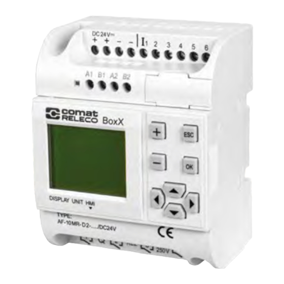
- Page 1 BoxX 2 series User Manual BoxX 2 series PLC is an upgraded version of BoxX series PLC. Before you use the product, please kindly read the manual carefully so as to ensure proper use of the product.
-
Page 2: Table Of Contents
4.2.2 BoxX 2 A2B2 interface ............21 5 Functional comparison ................23 6 Technical Parameters ................. 24 6.1 General technical parameters ............24 6.2 AF-10MR-A2/AF-20MR-A2 ............... 25 6.3 AF-10MT-D2/AF-20MT-D2 ............... 26 6.4 AF-10MR-D2/AF-20MR-D2 .............. 27 6.5 AF-10MT-E2/AF-20MT-E2 ............... 28 6.6 AF-10MR-E2/AF-20MR-E2 ............... 29... -
Page 3: Introduction
1 Introduction BoxX 2 series PLC is an upgraded version of old BoxX PLC, which is programmed by the use of a Function Block Diagram. The programming of BoxX 2 is simpler and easier to learn than that of a conventional PLC, which uses ladder diagrams and associated instructions. -
Page 4: Specifications And Models
BoxX 2 series PLC INTRODUCTION 1.2 Specifications and models Power Item Type Input Output supply 6 points AC digital AF-10MR-A2 AC110-220V 4 points relay output input AC/DC 6 points AC/DC AF-10MR-E2 4 points relay output 12-24V digital input 4 points transistor... -
Page 5: Boxx 2 Features
BoxX 2 series PLC user manual 1.3 BoxX 2 Features 1. Removable LCD display (AF-HMI) AF-HMI (Removable LCD display) can be used flexibly according to your needs.When you need it, you can install and use the keys on the panel to query/set the BOXX 2 address, BOXX 2 system time, modify the function block parameters and manually calibrate the analog quantity, etc.When you don't need it, you can disassemble it and replace it with an ordinary panel,... - Page 6 BOXX 2 series PLC INSTRODUCTION 6. Analog inputs BOXX 2 can receive analog input except for switch input so as to complete the control of temperature, humidity, pressure, flow, liquid level, etc., and can monitor the analog value status of the PC through short distance or long distance.And BOXX 2 simulation accuracy and BoxX greatly improved to 10 (0.1v) 7.
-
Page 7: Installation And Wiring
2 Installation and wiring 2.1 Installation 2.1.1 Methods BOXX 2 is small so it is suitable to be fit inside panels or machinery. The installation of BOXX 2 is extremely easy. 1. Use standard 35mm DIN rail mounting BOXX 2 2. -
Page 8: Dimensions(Unit:mm)
BOXX 2 series PLC Installation and Wiring 2.1.2 Dimensions Fig 2.2 AF2-10 Series(mm) Fig 2.3 AF2-20 Series(mm 2.2 Wiring of BOXX 2 Screwdriver with a spade tip width of 3mm is needed for the wiring of BOXX 2 series. As for the cross section of a wire. The following two sizes are at choice: * 1×2.5mm * 2×1.5mm... -
Page 9: Connection Of Power Supply
BOXX 2 series PLC user manual 2.2.1 Connection of power supply 1. For BOXX 2s like AF-10MR-A2 and AF-20MR-A2, its applicable power supply is 100~240VAC,50/60Hz.The grid voltage fluctuation range is about 10%. 2. For BOXX 2s like AF-10MR-D2,AF-20MR-D2,AF-10MT-D2,AF-20MT-D2,AF- 10MT-GD2, AF-20MT-GD2,AF-10MT-E2,AF-20MT-E2,Its applicable power supply voltage is DC12V-24V. - Page 10 BOXX 2 series PLC Installation and Wiring Proximity switch type with direct input 2-wire system/3-wire system/4-wire Note: 1. Analog can be input into analog-receivable BOXX 2s like AF-10/20MR-D2,AF-10/20MT-D2,AF-10/20MT-GD2 through all the input ports(I1-I6/I1-IC).As long as the analog-related function blocks are used in the program,Its port is automatically set to analog input.
-
Page 11: Boxx 2 Output Connection
BOXX 2 series PLC user manual 2.2.3 BOXX 2 output connection AF-10MR-A2/AF-20MR-A2/AF-10MR-E2/AF-20MR-E2/AF-10MR- D2/AF-20M R-D2 type BOXX 2 is the relay output, t he relay's contact to the power and input is isolated. AF -10MT-D2/AF-20MT- D2/AF-10MT-GD2/AF-20MT-GD2/AF-10MT-E2/AF-20 MT-E2 type BOXX 2 is the transistor output. - Page 12 BOXX 2 series PLC Installation and Wiring Fig 2.10 Transistor Output(D type) 2)Type GD connection is shown in Fig2.11, Fig 2.11 Transistor Output(GD type)
-
Page 13: Programming On Boxx 2 Panel
3 Programming on BOXX 2 panel BOXX 2 operation panel is a simple man-machine interface, which is Fig 3.1 completed by the following eight buttons to complete the panel operation. 3.1 BOXX 2 status display interface After the BOXX 2 is powered on, the AF-HMI enters the BOXX 2 status display interface. -
Page 14: Function Interface
BOXX 2 series PLC user manual When you press the +/- key for the first time, the password value is 0. You can use the left/right keys to move the password input position and enter the remaining number of password values. If the user password is entered correctly, it will enter the panel function interface;If the user password is not entered correctly, it will stay on the input password interface. -
Page 15: Fab/Rom Interface
BOXX 2 series PLC Panel Operation 3.3.1 FAB/Rom Interface When the user enters into the FAB/Rom interface as shown above, then when the user enters the Calibrate interface, Rom → FAB interface and FAB_Addr interface under the BOXX 2 function interface, the BOXX 2 machine will stop running. - Page 16 BOXX 2 series PLC user manual 2. When the minimum value is prompted, an external power supply is required to input the minimum voltage value for this channel, then press OK to confirm and mark as Vmin. When the maximum value is prompted,an external power supply is required to input the maximum voltage value for this channel.
- Page 17 BOXX 2 series PLC Panel Operation 1) Timing function block Time unit: Unit Unit(1-hour,2-minute,4-second) Int. Integer bit Decimal places As shown in Fig 3.8, B002 function block is MPLR single pulse function block,The parameter is 30.3 seconds.If you want to modify the parameter, pls kindly remove the cursor to the modified bit you need, then set up the parameter via+/- keys.
- Page 18 BOXX 2 series PLC user manual For example, as shown in Fig 3.10 B000 function block for SCHD clock switch week type, open Monday to Saturday 8:30. If you want to modify the parameter, you could remove the cursor to the modified bit you need, then set up the parameter via +/- key. B000 SCHD W 1-6 ON...
-
Page 19: Setting Interface
BOXX 2 series PLC Panel Operation FAB_Addr Fig 3.12 3.3.2 Setting interface When the user enters the Set.. setting interface on the BOXX 2 function interface, as shown in Fig 3.13 When the user enters the Set.. setting interface under the BOXX 2 function interface, the BOXX 2 system time and BOXX 2 password can be viewed or modified. -
Page 20: Communication Connection
4 Communication connection BOXX 2 series PLC not only has a download port custom protocol, but also supports Modbus RTU protocol, and can communicate with other devices that support modbus RTU protocol. The upper right side of the BOXX 2 is the program download port, as shown Fig 4.1 The upper left side of BOXX 2 front view is 485 interface, as shown in Fig 4.1 Program... -
Page 21: Boxx 2 A2B2 Interface
BOXX 2 series PLC Communication Address Read-write Function Comment Type Property Code Only Read Read the status of system(00-FF) Only Read Read status of digit input(100-1FF) Only Read Read status of AI(300-3FF) Only Read Read status of Output Q(200-2FF) 1: BoxX 2 is act as Modbus slave device, which responds according to the requested data by Modbus master device. - Page 22 BOXX 2 series PLC user manual BOXX 2 program programs (1-128) Reading input analog 1-12 Read value Reading parameter values of function blocks in BOXX 2 Read Corresponding Register programs block number in Write parameter values of the BOXX 2 function blocks in BOXX 2 Write program...
-
Page 23: Functional Comparison
5 Functional comparison The BOXX 2 series PLC is an upgraded version of the BoxX series PLC. The function comparison diagrams of the two are as follows: Item BoxX BoxX 2 Basic features 100h 160h 25℃RTC buffer RTC accuracy 150s/month 20s/month Password Protection Yes(*protection) -
Page 24: Technical Parameters
6 Technical Parameters 6.1 General technical parameters Item Basis Condition Climate environment Cold:EC68-2-1 Humidity Heat:IEC68-2-2 Horizontal installation -20°C'-70°C Vertical -20°C'-70°C installation Storage/Transpo -40°C'-70°C rtation Relative IEC68-2-30 5%'-95% without condensation humidity Atmospheric 795-1080Kpa pressure 10cm ,4days IEC68-2-42 Pollutants S 1cm ,4days IEC68-2-43 Mechanical environment Protection type... -
Page 25: Af-10Mr-A2/Af-20Mr-A2
IEC/VDE safety information Insulation IEC1131 Meet the requirements Intensity 25℃ clock buffer Typical 100h menory RTC accuracy ±Max 20S/Month 6.2 AF-10MR-A2/AF-20MR-A2 Power Supply The rated voltage of power supply AC100-240V Allowable range of the rated input voltages AC85-260V VDE0631: AC85-260V IEC1131:... -
Page 26: Af-10Mt-D2/Af-20Mt-D2
BOXX 2 series PLC Technical Parameters Fluorescent Light Tube With Regular 1×58W(AC230/240V) Compensation(25,000Switch cycles) Fluorescent Light Tube without Compensation 10×58W(AC230/240V) (25,000 Switch Cycles) Power Supply ProtectionB16 Short Circuit Protectioncos1 600A Power Supply ProtectionB16 Short Circuit Protection 900A cos0.5-0.7 Max.20A Output Relay Protection FeatureB16 Switch Frequency Machine... -
Page 27: Af-10Mr-D2/Af-20Mr-D2
BOXX 2 series PLC user manual Current limit of short circuit about 2A No( even in the whole Reduction of the rated value temperature range) 6.4 AF-10MR-D2/AF-20MR-D2 Power Supply The rated Voltage of power supply DC12/24V Allowable range of the rated input DC10-28V voltage Power Consumption (DC24V) -
Page 28: Af-10Mt-E2/Af-20Mt-E2
BOXX 2 series PLC Technical Parameters Switch Frequency Max. 20A FeatureB16 Machine Resistor Load/Lamp Load 10Hz Induced Load Output Type 0.5Hz 6.5 AF-10MT-E2/AF-20MT-E2 Power supply The rated Voltage of power supply DC12/24V Allowable range of the rated input DC10V-28V voltage Typical 80mA Power Consumption (DC24V) (Output full load) -
Page 29: Af-10Mr-E2/Af-20Mr-E2
BOXX 2 series PLC user manual 6.6 AF-10MR-E2/AF-20MR-E2 Power supply The rated Voltage of power supply AC/DC12V-AC/DC24V Allowable range of the rated input AC/DC10V-28V voltage Power Consumption (AC/DC24V) A F - 1 0 M R - E ( 3 W ) (Output full load) A F - 2 0 M R - E ( 5 W ) Digital Input... -
Page 30: Af-10Mt-Gd2/Af-20Mt-Gd2
BOXX 2 series PLC Technical Parameters Resistor Load/Lamp Load Induced Load 0.5Hz 6.7 AF-10MT-GD2/AF-20MT-GD2 Power supply Supply voltage rating DC12/24V Fluctuation voltage allowable range DC10V-28V Typical 80mA Consumption(DC24V) (Output full load) Typical 2W Input section(digit input) Signal 0 <DC3.5V Signal 1 DC10-24V Input current of signal 1 <2.5mA...
Need help?
Do you have a question about the AF-10MR-A2 and is the answer not in the manual?
Questions and answers